Fiber laser with cladding-to-core energy migration

a fiber laser and energy migration technology, applied in the direction of cladded optical fibre, active medium materials, instruments, etc., can solve the problems of ineffective energy transfer from the pumping source to the core element, the method and other conventional methods of pumping the cladding element are deficient, and the power density of the optical fiber laser structure can be developed with the power density,

Inactive Publication Date: 2004-04-22
KIGRE
View PDF5 Cites 2 Cited by
  • Summary
  • Abstract
  • Description
  • Claims
  • Application Information

AI Technical Summary

Benefits of technology

0013] FIG. 2 is a cross-sectional view of the optical fiber laser structure including more than one core element; and

Problems solved by technology

As a result, optical fiber laser structures can be developed with power densities that are only limited by material considerations and the ability to introduce energy, through the pumping sources, into the optical fiber laser structure.
This method, and other conventional methods of pumping the cladding element, are deficient for various reasons.
The method disclosed in the '501 patent is deficient because, to effectively transfer energy from the pumping source to the core element, this method requires pumping of an active gain component in the cladding element, specifically Nd, such that the active gain component in the cladding element actually lases.
If lasing is not achieved in the cladding element, then the energy is not effectively transferred from the pumping source to the core element, i.e., the core element does not lase.
Reliance on lasing to transfer energy from the cladding element to the core element creates a range of difficulties in utilizing this technology.
The method of pumping the cladding element of the optical fiber laser structure disclosed in U.S. Pat. No. 5,530,710 is deficient for similar reasons.
This method is, therefore, unable to directly pump a three-level active gain component without relying on first pumping of the intermediate four level active gain component.

Method used


Image

  • Fiber laser with cladding-to-core energy migration
  • Fiber laser with cladding-to-core energy migration

Examples


first embodiment

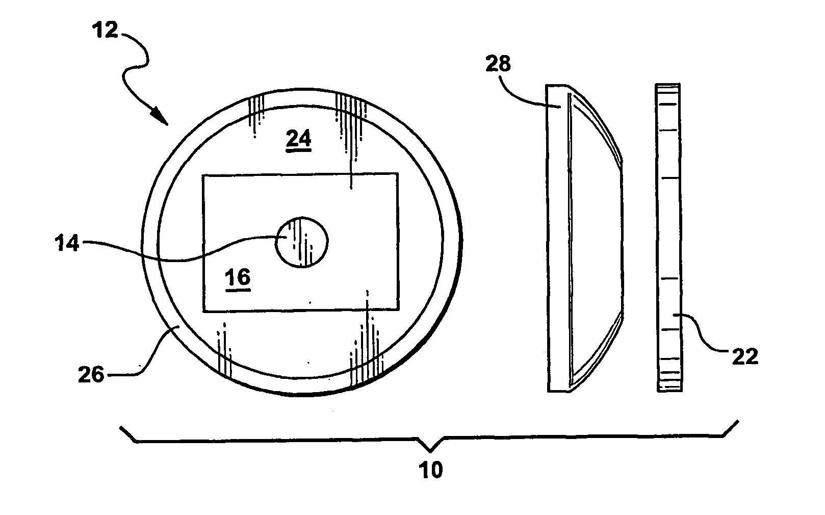
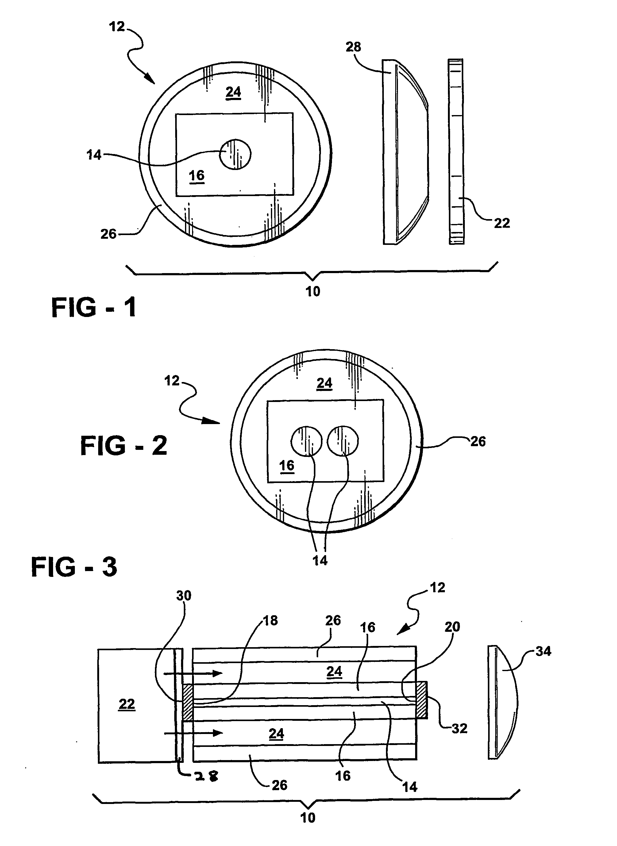
[0022] In the first embodiment, where the active gain component in the core element 14 is Yb, the energy migration component in the cladding element 16 preferably is Yb. In this embodiment, the Yb in the cladding element 16 is present in an amount from 5 to 50, preferably from 10 to 40, and most preferably from 12 to 30, parts by weight based on 100 parts by weight of the cladding element 16. In this embodiment, the concentration of Yb in the core element 14 is significantly lower than the concentration of Yb in the cladding element 16 to lower the threshold for lasing or for providing gain in the core element 14. Thus, the energy is pumped into the cladding Yb element 16 wherein the high level of Yb transfers the energy to the core element 14. The low level of Yb in the core element 14, relative to the level in the cladding element 16 causes the Yb in the core element 14 to lase. Thus, in this embodiment the energy migration component and the active gain component are the same spec...

second embodiment

[0023] In the second embodiment, where the active gain component in the core element 14 is Er, the energy migration component in the cladding and core elements 16, 14 preferably includes Yb. In this embodiment, the Yb in the cladding and core elements 16, 14 is present in an amount from 5 to 50, preferably from 10 to 40, and most preferably from 12 to 30, parts by weight based on 100 parts by weight of the cladding element 16 or core element, respectively. In this embodiment, where Er functions as the active gain component and Yb functions as the energy migration component, the subject invention incorporates an energy migration component and an active gain component are different species. Using Yb in the core element 14 and the cladding element 16 permits the energy to continue to migrate throughout an entire volume of the core element 14 and, at the same time, act as the sensitizing component to the Er. Using Yb as the sensitizing component in this embodiment is described further b...

fourth embodiment

[0024] In the fourth embodiment, where the active gain component in the core element 14 includes Ho, the energy migration component in the core and cladding elements 14, 16 preferably includes ytterbium (Yb). In this embodiment, the Yb in the cladding element 16 and in the core element 14 is present in an amount from 5 to 50, preferably from 10 to 30, and most preferably from 15 to 25, parts by weight based on 100 parts by weight of the cladding element 16 and core element 14. Furthermore, in this embodiment, where Ho functions as the active gain component and Yb functions as the energy migration component, the subject invention further incorporates Tm in the core element 14 as a sensitizing component to the Ho. Using Tm as the sensitizing component in this embodiment is described further below.

[0025] In further alternative embodiments, the energy migration component in the cladding element 16 can comprise europium (Eu), terbium (Tb), cerium (Ce), and combinations thereof.

[0026] The...


PUM


Abstract

A method of transferring energy in an optical fiber (12) from the fiber's cladding element (16) of the fiber's core element (14) is disclosed. The core element (14) includes an active gain component and an energy migration component, and the cladding element (16), which surrounds the core element (14), includes the energy migration component. The method includes the steps of providing a pump (22) for producting energy and optically coupling the pump with the cladding element (16), such that the energy is absorbed and stored in the cladding element (16) by its energy migration component. A further step includes the active gain component in the core element (14) lasing or providing gain, when the transferring of energy from the cladding element's energy migration component to the core element's energy migration component takes place.

Description

[0001] 1) Field of the Invention[0002] The subject invention generally relates to a method of transferring energy in an optical fiber amplifier or laser structure. More specifically, the subject invention relates to a method of transferring energy from a cladding element to a core element by migration of the energy within an energy migration component found in the cladding and core elements to an active gain component in the core element. In some embodiments the core element includes a sensitizer in addition to the energy migration component and the active gain component. In other embodiments, the energy migration component located in the core elements functions as the active gain component.[0003] 2) Description of Related Art[0004] Methods of transferring energy in optical fiber amplifiers and laser structures are known in the art. To transfer energy, many of these methods rely on pumping the cladding elements of the optical fiber amplifier or laser structures. As is known in the a...

Claims


Application Information

Patent Timeline
Patent Type & Authority Applications(United States)
IPC IPC(8): H01S3/067H01S3/16
CPCH01S3/067H01S3/1698H01S3/06716H01S3/06708
Inventor MYERS, JOHN D.MYERS, MICHAEL J.
Owner KIGRE
Why Eureka
Try Eureka