Robot controller

a robot controller and controller technology, applied in the field of robot controllers, can solve the problems of single circuit for stopping the robot, no countermeasures are provided for cases, and the robot is not provided in the emergency stopper, so as to achieve the effect of high reliability

Active Publication Date: 2004-04-22
FANUC LTD
View PDF5 Cites 48 Cited by
  • Summary
  • Abstract
  • Description
  • Claims
  • Application Information

AI Technical Summary

Benefits of technology

0028] The present invention makes it possible to improve a robot controller in which a portable teaching operating part comprising emergency stop operating means for placing the robot in an emergency-stop state and emergency stop release operating means for releasing this e

Problems solved by technology

In this technique, the robot control part can ascertain the occurrence of an abnormality by the fact that there is no response from the teaching box, and can cause emergency stopping of the robot.
However, in both of these conventional techniques, as was described above, only a single circu

Method used


Image

  • Robot controller
  • Robot controller
  • Robot controller

Examples


embodiment 1

[0042] [Embodiment 1]

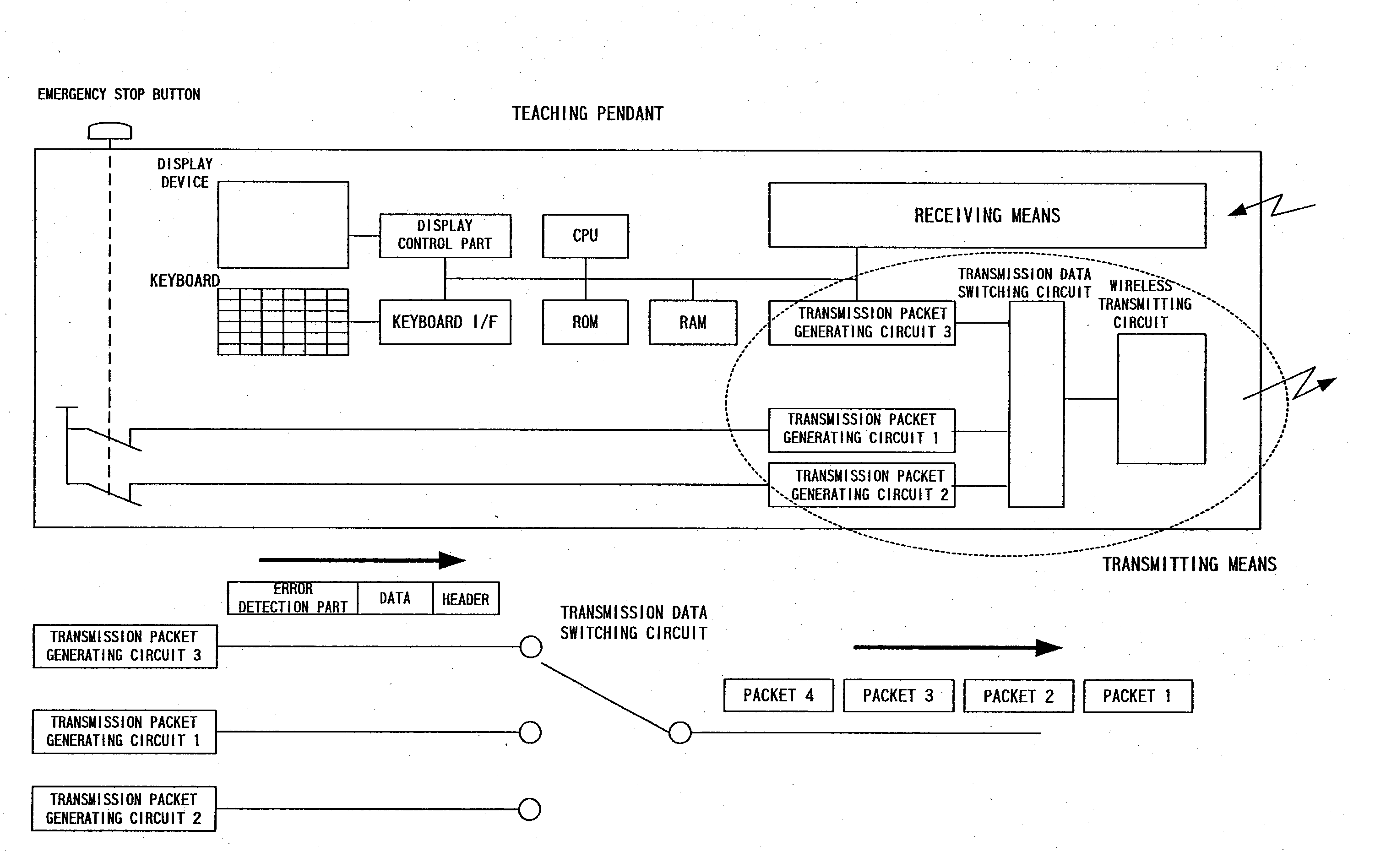
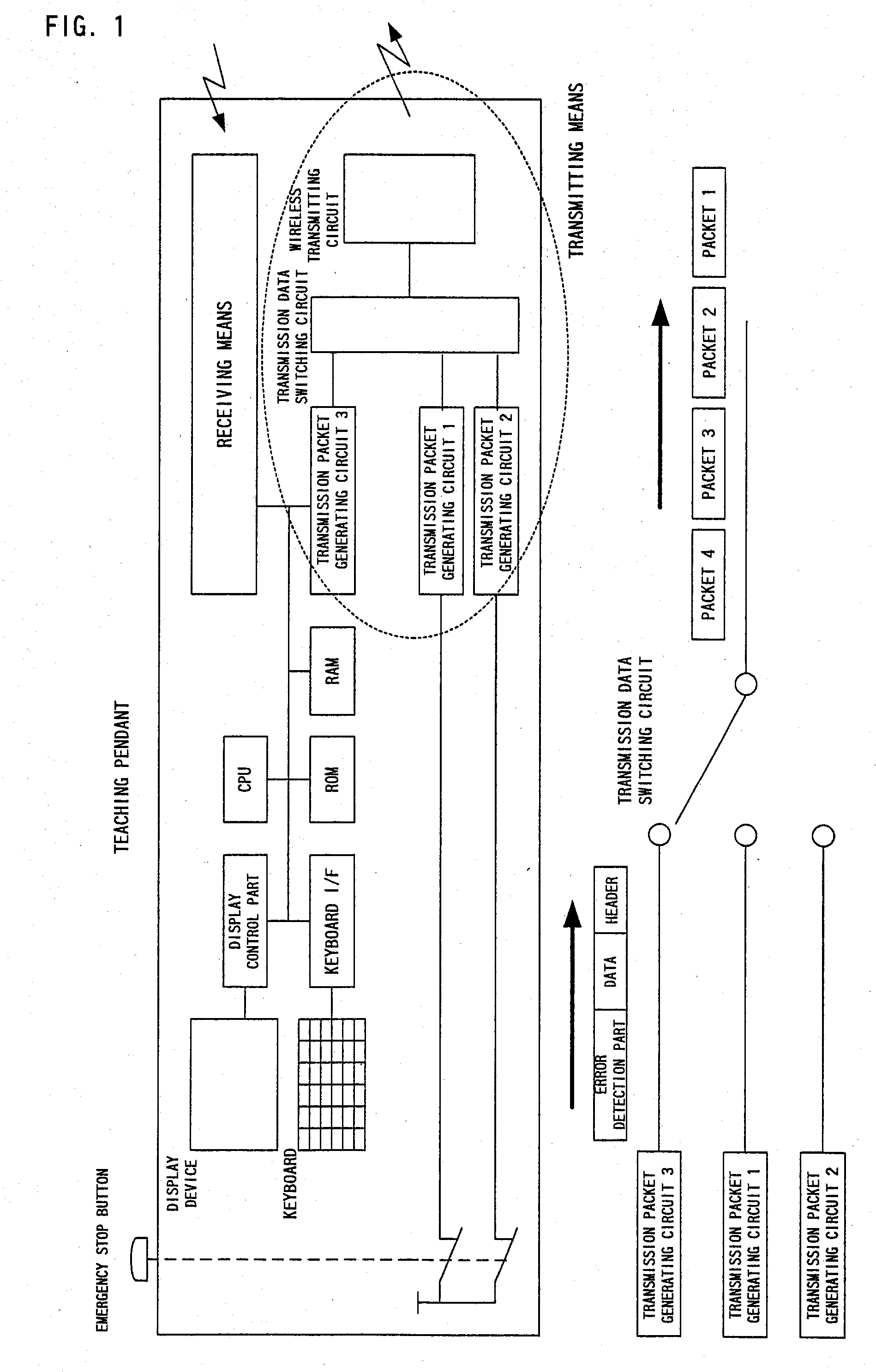
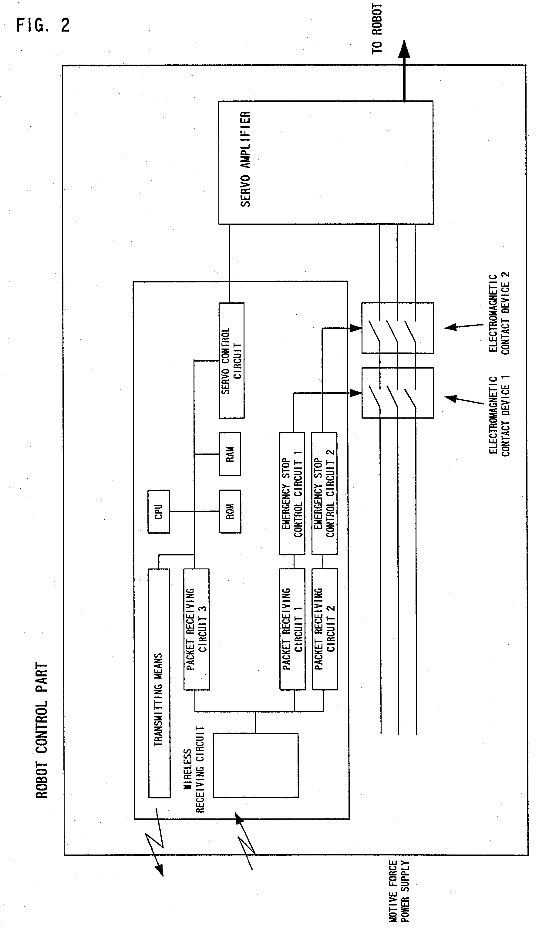
[0043] Fig. 1 is a diagram which illustrates the teaching pendant used in Embodiment 1. This figure shows a schematic diagram of the panel with an emphasis on parts relating to the generation, transmission, reception and the like of emergency stop signals. Furthermore, Fig. 2 is a diagram which illustrates the robot control part used in Embodiment 1. This figure shows a schematic diagram of the robot control part with an emphasis on communications relating to the emergency stopping of the robot and parts relating to the control of the robot.

[0044] First, with reference to Fig. 1, the teaching pendant that constitutes a portable teaching operating part has a CPU, and a ROM, RAM, display control part and keyboard interface that are connected to this CPU; a display device (e. g., a liquid crystal display) is connected to the display control part, and a keyboard (disposed on the teaching pendant) is connected to the keyboard interface.

[0045] Furthermore, receiving m...

embodiment 2

[0072] [Embodiment 2]

[0073] Fig. 5 is a diagram which illustrates the teaching pendant used in Embodiment 2. This figure shows a schematic diagram of the panel with an emphasis on parts relating to the generation, transmission, reception and the like of emergency stop signals. Furthermore, Fig. 6 is a diagram which illustrates the robot control part used in Embodiment 2. This figure shows a schematic diagram with an emphasis on communications relating to the emergency stopping of the robot, and parts relating to the control of the robot.

[0074] The present embodiment uses a system which is devised so that one of the two emergency stop signals in Embodiment 2 is read from the CPU, and the CPU transmits communications data originating in this emergency stop signal to the control part side via transmitting means. In the present embodiment, a case is indicated in which the CPU that reads the emergency stop signal also has the function of controlling the display device and keyboard of the...

embodiment 3

[0097] [Embodiment 3]

[0098] Fig. 7 is a diagram which illustrates the teaching pendant used in Embodiment 3 and shows a schematic diagram of the panel with an emphasis on parts relating to the generation, transmission, reception and the like of emergency stop signals. In the present embodiment, two emergency stop signals are respectively read by separate CPUs, and so that the respective CPUs transmit data relating to the need for emergency stopping to the control part side via transmitting means. The two CPU circuits are connected to separate paths, and operate independently; however, the respective CPU circuits monitor the normal operation of each other by exchanging information via a shared memory. If one CPU detects that the other CPU is not operating normally, this CPU notifies the control part via its own transmission data generating circuit, and the robot is safely stopped on the robot control part side.

[0099] Referring to Fig. 7, the teaching pendant which constitutes a porta...


PUM


Abstract

Abstract of the Disclosure When the emergency stop button on the teaching pendant is pressed, the packet generating circuits 1 and 2 each prepare packet data relating to emergency stopping, and transmit this data to the robot control part by wireless communications via the transmission data switching circuit. Besides data indicating the need or lack of need for emergency stopping, a header or the like designating the packet receiving circuit to which the transmission is addressed is added to the packet data. The respective packet receiving circuits of the robot control part receive the respective sets of packet data in accordance with the designations of the headers. When the emergency stop button is pressed, emergency stop signals are output to a plurality of emergency stop control circuits from the respective packet receiving circuits immediately afterward, and a plurality of contacts connected in series are placed in a non-conductive state, so that the supply of motive force to the servo amplifiers is cut off, thus causing the robot to make an emergency stop.

Description

Detailed Description of the InventionBackground of Invention[0001] 1.Field of the Invention[0002] The present invention relates to a robot controller, and more particularly relates to a robot controller in which a portable instruction and operating part comprising emergency stop operating means that place the robot in an emergency-stop state and emergency stop release operating means that release this emergency-stop state is connected by wireless communications with an control part that controls the robot.[0003] 2.Description of the Related Art[0004] The connection of a portable teaching operating part equipped with an emergency-stop button or the like as emergency stop operating means used to cause emergency stopping of a robot, and a control part used to control the robot, by means of wireless communications, so that the operator can cause emergency stopping of the robot by operating the emergency-stop button or the like installed in the portable teaching operating part, is a conv...

Claims


Application Information

Patent Timeline
IPC IPC(8): B25J13/06B25J19/00B25J19/06G05B9/02G05B19/18G08C17/00
CPCB25J13/06B25J19/06G05B9/03G08C17/00G05B2219/36162G05B2219/50198G05B2219/33192Y02P90/02
Inventor HASHIMOTO, YOSHIKIKUBO, YOSHIYUKI
Owner FANUC LTD
Why Eureka
Try Eureka