Pneumatic radial tires

a radial tire and pneumatic technology, applied in the direction of wheels, vehicle components, transportation and packaging, etc., can solve the problems of insufficient control of the occurrence of belt end separation, inability to use the tire, and slight cracks in the rubber located

Inactive Publication Date: 2004-04-29
BRIDGESTONE CORP
View PDF7 Cites 0 Cited by
  • Summary
  • Abstract
  • Description
  • Claims
  • Application Information

AI Technical Summary

Benefits of technology

[0009] When the cords embedded in the widthwise outer end portions of the maximum-width belt layer and the narrow-width belt layer arrive at a ground contact region during the running of the pneumatic radial tire, a diamond shape defined by these cords is deformed in a crushed direction due to the influence of a crown curvature, whereby the widthwise outer end of the narrow-width belt layer displaces inward in the widthwise direction at maximum. Therefore, when the reinforcing layer is arranged so as to overlap with the widthwise outer end portion of the maximum-width belt layer located outward from the widthwise outer end of the narrow-width belt layer in the widthwise direction and contains many cords arranged in an oppositely inclination direction to the cords of the maximum-width belt layer, a diamond shape defined by the cords embedded in the reinforcing layer and the cords embedded in the maximum-width belt layer are also deformed in a crushed direction due to the same tensional deformation in the circumferential direction as mentioned above, so that the reinforcing layer, widthwise outer end portion of the maximum-width belt layer and rubber surrounding them (including rubber located outward from the widthwise outer end of the narrow-width belt layer in the widthwise direction) displace inward in the widthwise direction together, whereby the tensile strain in the widthwise direction produced at the boundary between the widthwise outer end of the narrow-width belt layer and the rubber located outward from the widthwise outer end in the widthwise direction is decreased (or it is a compression strain according to circumstances). As a result, the occurrence and development of cracks in the rubber located in the vicinity of cord ends of the narrow-width belt layer are effectively controlled and hence the belt end separation is effectively prevented.
[0010] In a preferable embodiment of the invention, the cords of the reinforcing layer are inextensible cords and the reinforcing layer is closely arranged at the inside of the maximum-width belt layer in the radial direction, or the widthwise outer end of the reinforcing layer is located inward from the widthwise outer end of the maximum-width belt layer in the widthwise direction, whereby the belt end separation of the narrow-width belt layer can surely be prevented while controlling the separation failure at the widthwise outer end of the reinforcing layer.
[0011] In another preferable embodiment of the invention, the widthwise inner end of the reinforcing layer is located in the vicinity of the widthwise outer end of the narrow-width belt layer and an inclination angle A of the cord embedded in the reinforcing layer with respect to the equatorial plane of the tire is within a range of 4.degree. to 60.degree.. In this case, the belt end separation of the narrow-width belt layer can further be prevented.
[0012] In the other preferable embodiment of the invention, the reinforcing layer is extended inward in the widthwise direction so as to form a one-piece body on the equatorial plane and an inclination angle B of the cord embedded in the reinforcing layer is not less than 34.degree. with respect to the equatorial plane. In this case, the hoop effect of the belt can be enhanced while simplifying the production.
[0013] In a further preferable embodiment of the invention, the cords of the reinforcing layer are organic fiber cords and the reinforcing layer is arranged at the outside of the maximum-width belt layer in the radial direction. Even in this case, the belt end separation of the narrow-width belt layer can effectively be prevented.

Problems solved by technology

In this type of the tire, there has recently been caused a problem that cracks are created at a side end of a belt layer in a widthwise direction thereof in the use over a long time of period and grow inward in the widthwise direction or outward in the radial direction between the belt layers with the lapse of time to cause a separation failure and hence make the use of the tire impossible.
And also, such a deformation is caused when the tread end portion of the tire rides on projections such as stones and the like during the running on bad road to largely deform rubber in this end portion.
Moreover, the ends of the cords embedded in the belt layer are exposed at the outer end of the belt layer in the widthwise direction and are cut faces not subjected to brass plating or the like for enhancing an adhesion to rubber, so that the ends of the cords are repeatedly pulled apart from the surrounding rubber due to the influence of the above tensile strain and hence slight cracks are created in the rubber located in the vicinity of the cord ends exposed at the outer end of the belt layer in the widthwise direction.
However, these methods can develop an effect to a certain level, but have a problem that the occurrence of the belt end separation can not sufficiently be controlled.

Method used


Image

  • Pneumatic radial tires
  • Pneumatic radial tires
  • Pneumatic radial tires

Examples


first embodiment

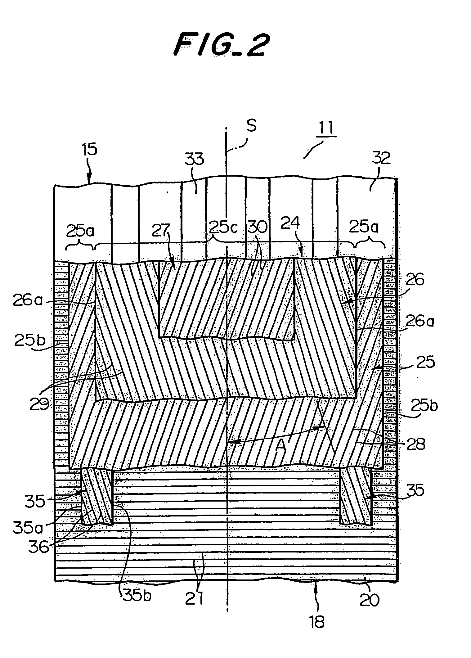
[0025] In FIGS. 1 and 2, numeral 11 is the heavy duty pneumatic radial tire for use in truck and bus according to the invention. The tire 11 comprises a pair of bead portions 13, a pair of sidewall portions 14 extending outward from these bead portions 13 in a radial direction of the tire, and a tread portion 15 of an approximately cylindrical form connecting radially outer ends of the sidewall portions 14 to each other. Further, the tire 11 comprises a carcass 18 toroidally extending between a pair of bead cores 17 embedded in the bead portions 13 and reinforcing the sidewall portions 14 and the tread portion 15. Each end portion of the carcass 18 is wound around the bead core 17 provided with a stiffener 19 from inside of the tire toward outside thereof. The carcass 18 is comprised of at least one rubberized carcass ply, one carcass ply 20 in this embodiment, which contains many inextensible cords 21 such as steel cords embedded therein and extending substantially in the radial di...

third embodiment

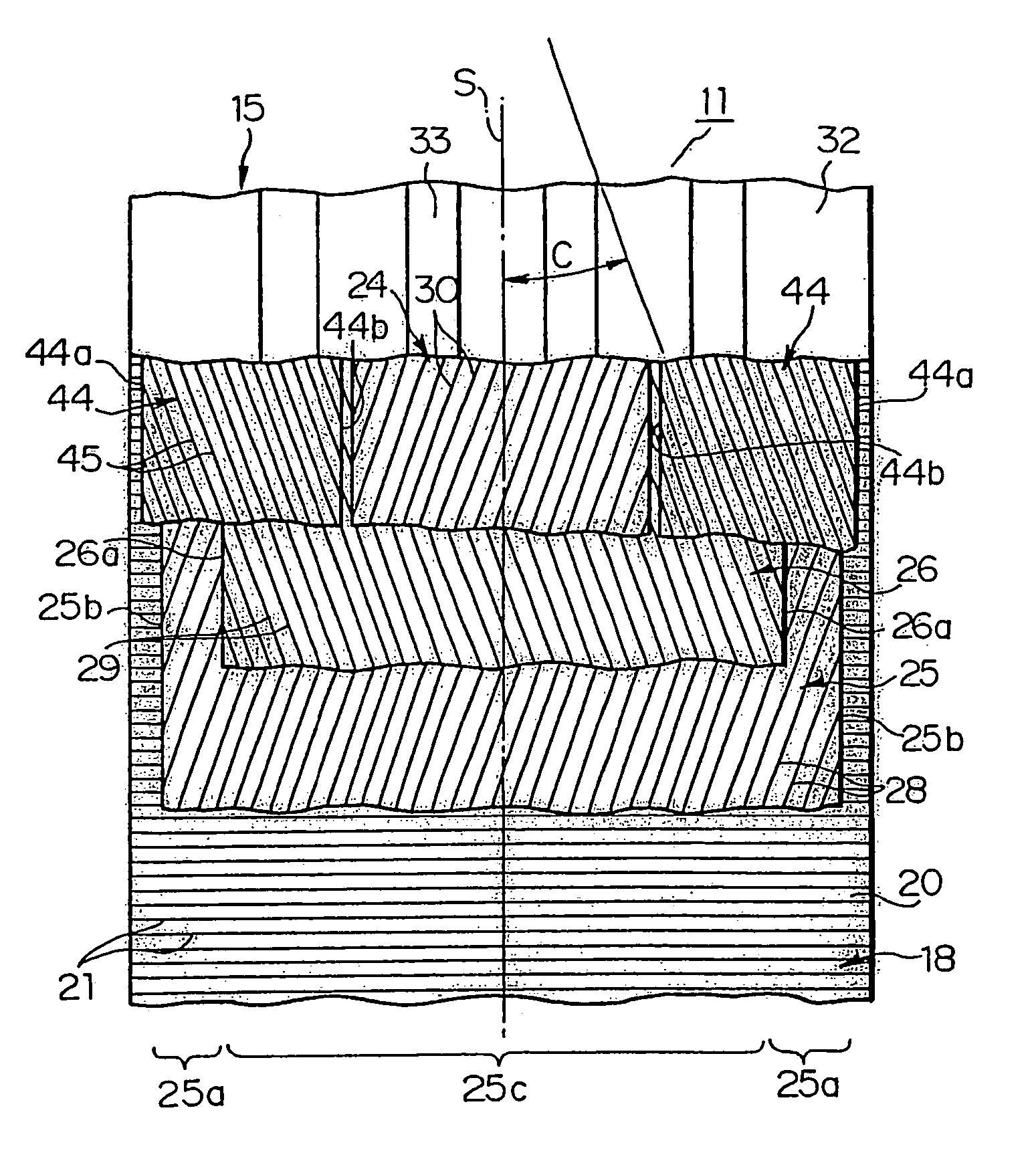
[0039] Then, the invention is described with reference to FIGS. 7 and 8. In this embodiment, a reinforcing layer 44 is comprised of organic fiber cords 45 having a small stiffness instead of the inextensible cord such as steel cord. Since the organic fiber cord is low in the influence upon the cord 28 at the widthwise outer end portion 25a, if the reinforcing layer 44 is arranged at the inside of the maximum-width belt layer 25 in the radial direction, rubber located at the outside of the widthwise outer end portion 25a in the radial direction can not sufficiently be displaced inward in the radial direction. For this end, it is necessary that when the cord 45 is the organic fiber cord, the reinforcing layer 44 is arranged at the outside of the widthwise outer end portion 25a in the radial direction to sandwich rubber located at the outside of the widthwise outer end portion 25a in the radial direction between the widthwise outer end portion 25a and the reinforcing layer 44, whereby ...


PUM


Abstract

In a pneumatic radial tire comprising a belt of at least two belt layers, in which the belt comprises a maximum-width belt layer containing many cords slantly arranged with respect to an equatorial plane of the tire and a narrow-width belt layer arranged at the outside of the maximum-width belt layer in the radial direction and containing many cords arranged in an oppositely inclined direction to the cords of the maximum-width belt layer, the belt end separation is controlled by arranging a reinforcing layer containing many cords arranged in an oppositely inclined direction to the cords of the maximum-width belt layer so as to overlap with an outer end portion of the maximum-width belt layer located outward from an outer end. of the narrow-width belt layer in the widthwise direction thereof.

Description

[0001] 1. Field of the Invention[0002] This invention relates to a pneumatic radial tire capable of controlling separation failure at belt end.[0003] 2. Description of Related Art[0004] There are known pneumatic radial tires for truck, bus and the like, which are particularly used under a heavy load and recapped plural times after the wearing of a tire tread. In this type of the tire, there has recently been caused a problem that cracks are created at a side end of a belt layer in a widthwise direction thereof in the use over a long time of period and grow inward in the widthwise direction or outward in the radial direction between the belt layers with the lapse of time to cause a separation failure and hence make the use of the tire impossible. Such cracks are considered to be created due to the following fact. That is, an end portion of the tread in the pneumatic radial tire is subjected to a tensional deformation in the circumferential direction every the contacting with a flat r...

Claims


Application Information

Patent Timeline
Patent Type & Authority Applications(United States)
IPC IPC(8): B60C9/18B60C9/20B60C9/22B60C9/28
CPCB60C9/2009B60C9/28Y10T152/10792Y10T152/10801Y10T152/10765B60C2009/2041
Inventor KADOTA, KUNINOBU
Owner BRIDGESTONE CORP
Why Eureka
Try Eureka