
Vehicle air conditioner

a technology for air conditioners and vehicles, applied in space heating and ventilation control systems, heating types, lighting and heating apparatuses, etc., can solve the problems of easy sense of air-blowing noise, further deterioration of heating feeling given to passengers, and easy sense of uncomfortable feeling for passengers

Inactive Publication Date: 2004-04-29
DENSO CORP
View PDF13 Cites 7 Cited by
  • Summary
  • Abstract
  • Description
  • Claims
  • Application Information

AI Technical Summary

Benefits of technology

[0009] It is a second object of the present invention to restrict cool air from being blown to the upper side of a passenger in the passenger compartment in an initial time of a bi-level mode in the warming-up control.
[0010] According to the present invention, in a vehicle air conditioner, a mode switching member for opening and closing a face opening and a foot opening is disposed to set at least a foot mode where the mode switching member closes the face opening and opens the foot opening, a fixed bi-level mode where the mode switching member opens both of the face opening and the foot opening by a predetermined fixed air-blowing ratio between air blown from the face opening and air blown from the foot opening, and a linear bi-level mode where an air blowing ratio from the foot opening and an air blowing ratio from the face opening are gradually changed as a time passe. Further, a control unit controls the mode switching member to perform the linear bi-level mode between the foot mode and the fixed bi-level mode, in a warming-up control in which a temperature of air to be blown into the passenger compartment is increased by the heating heat exchanger after a start of a heating operation for heating the passenger compartment. Accordingly, it can prevent the air-blowing ratio between air blown from the face opening and air blown from the foot opening from being suddenly changed.
[0011] Specifically, in the linear bi-level mode, an air blowing ratio from the foot opening is reduced and an air blowing ratio from the face opening is increased as a time passe. In this case, the control unit controls the mode switching member to perform the foot mode, the linear bi-level mode and the fixed bi-level mode in this order as the time passes in the warming-up control. Accordingly, variations in the air blowing ratio and in an air-blowing noise due to an air-outlet mode switching from the foot mode to the fixed bi-level mode, can be effectively reduced. Thus, uncomfortable feeling due to the air-outlet mode switching in the warming-up control, can be restricted from being given to the passenger. When the linear bi-level mode is ended, the increase of the air blowing ratio from the face opening is completed. Therefore, it can prevent cool air from being blown to the upper side of a passenger in the initial time of the bi-level mode. Further, in the fixed bi-level mode, conditioned air can be blown to the foot portion and the upper portion of the passenger while the air blowing ratio is maintained at a state where the increase of the air blowing amount from the face opening is completed. Accordingly, in the fixed bi-level mode, the whole body of the passenger can be effectively warmed.
[0012] Preferably, the mode switching member is disposed to further set an another linear bi-level mode in which the air blowing ratio from the foot opening is increased while the air blowing ratio from the face opening is reduced, as compared with the fixed bi-level mode, as the time passes. In this case, the control unit controls the mode switching member to perform the another linear bi-level mode and the foot mode in this order after the fixed bi-level mode is performed. Accordingly, the air-outlet mode change from the fixed bi-level mode to the foot air outlet mode can be smoothly performed through the another bi-level mode. Accordingly, the air-blowing ratio between the upper and lower sides of the passenger compartment can be smoothly changed, and air blowing noise can be gradually changed. Accordingly, air-conditioning feeling given to the passenger can be further improved.

Problems solved by technology

Further, at this time, air-blowing noise is readily sensed due to the sudden air blowing toward the face portion of the passenger.
Accordingly, when the air outlet mode is switched simply between the foot mode and the bi-level mode in the warming-up control, uncomfortable feeling may be given to the passenger.
Accordingly, when the air outlet mode is switched to the bi-level mode in the rear air-conditioning unit, heating feeling given to the passenger is further deteriorated.
Thus, uncomfortable feeling due to the air-outlet mode switching in the warming-up control, can be restricted from being given to the passenger.

Method used


Image

  • Vehicle air conditioner
  • Vehicle air conditioner
  • Vehicle air conditioner

Examples


first embodiment

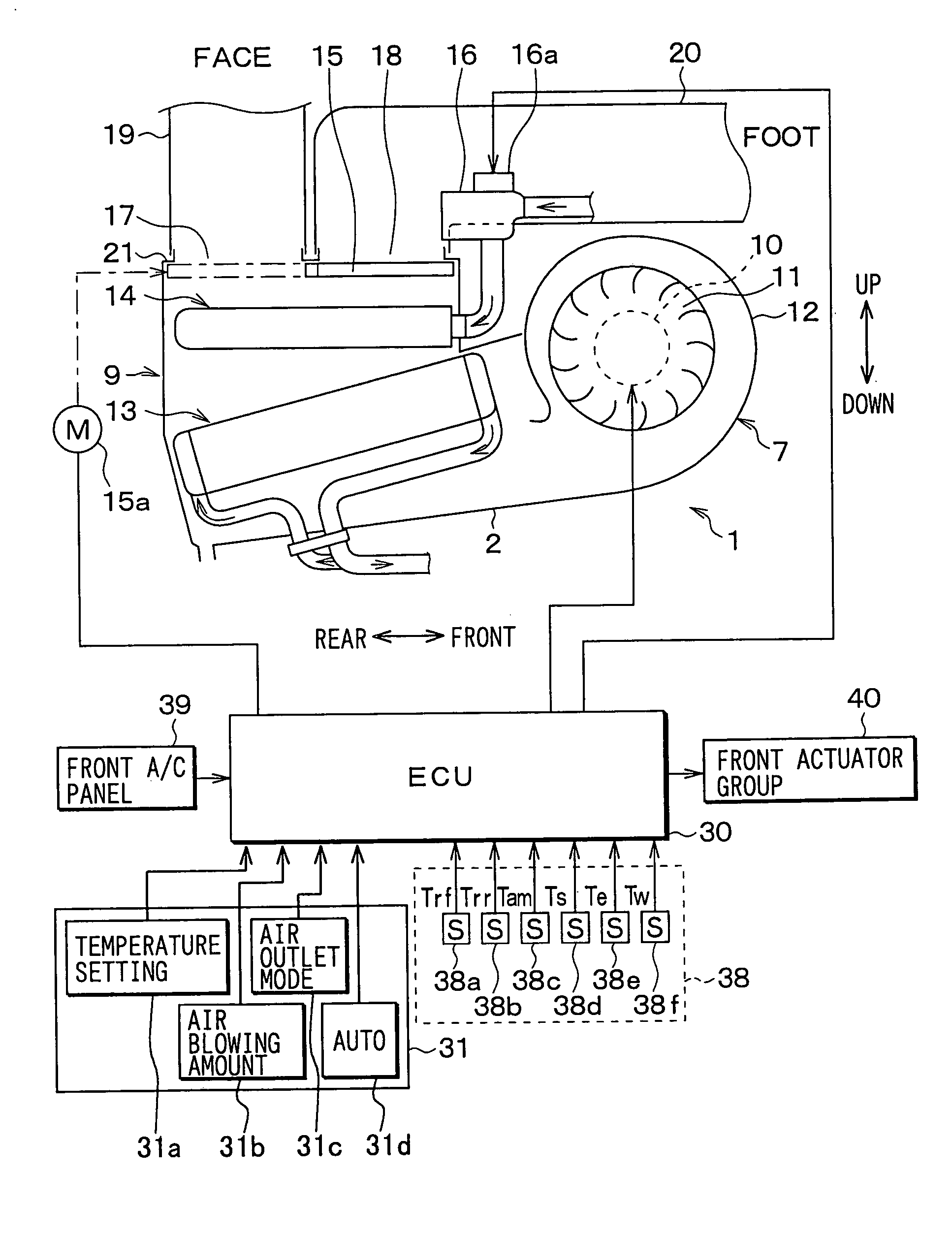
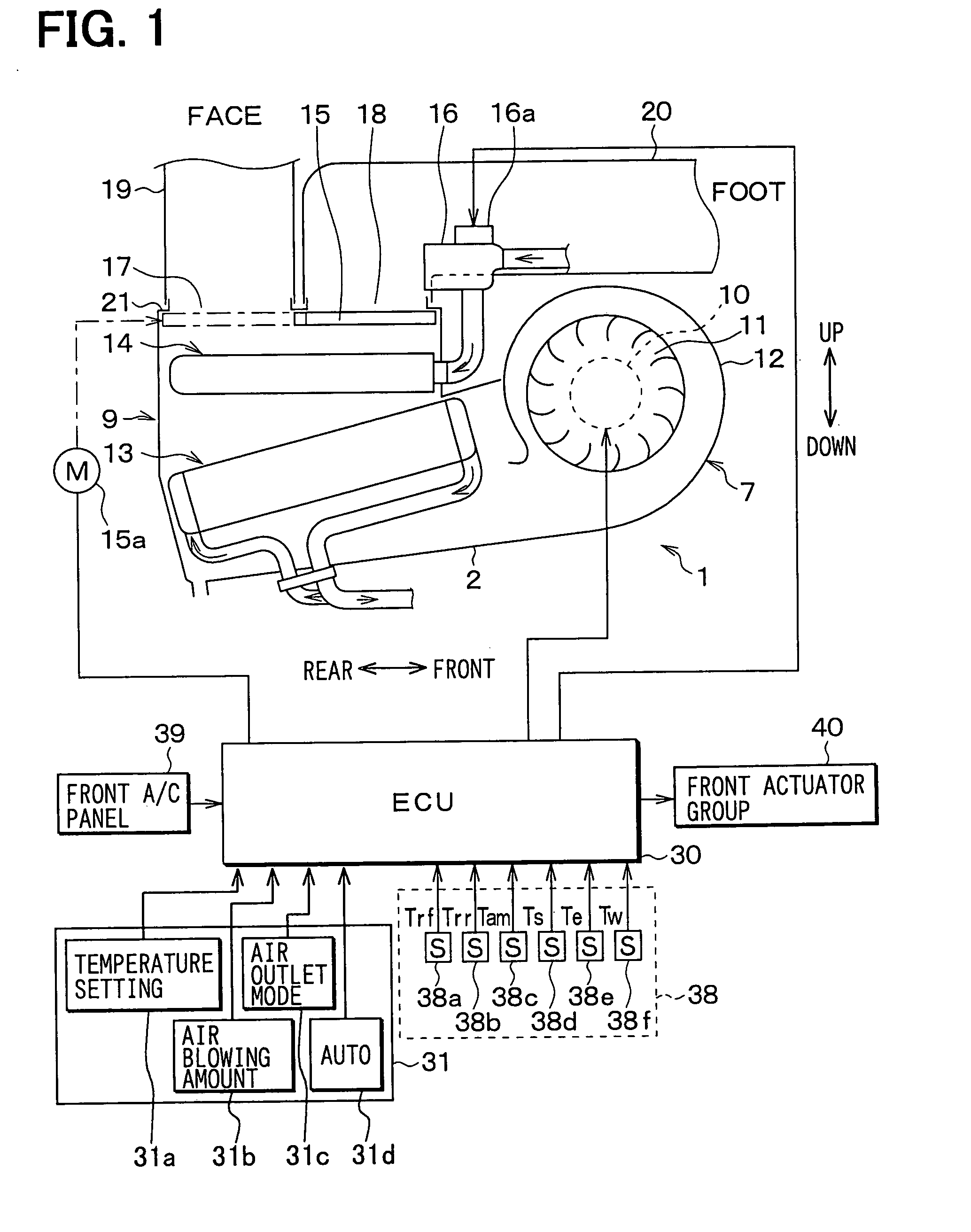
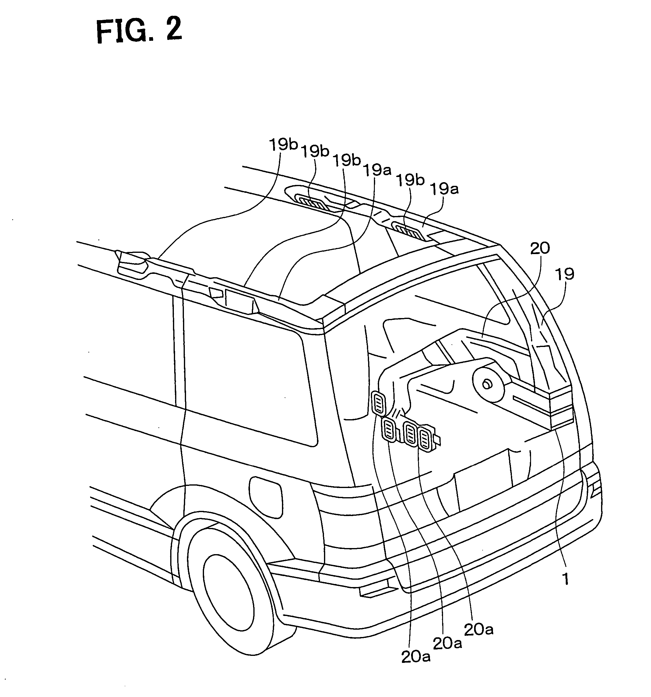
[0033] The first embodiment of the present invention will be now described with reference to FIGS. 1-10. In the first embodiment, the present invention is typically applied to a rear air conditioning unit 1 of a vehicle air conditioner. As shown in FIG. 1, the rear air-conditioning unit 1 includes an air-conditioning case 2 made of a resin material (e.g., polypropylene). The air-conditioning case 2 is constructed with plural separated case parts that are integrally assembled together to form an air passage therein. The rear air-conditioning unit 1 includes a blower 7, and a heat-exchanging unit 9 having a cooling portion and a heating portion that are integrated together. In FIG. 2, the rear air-conditioning unit 1 is provided in a vehicle side wall around a rear floor surface in a cargo room of a wagon car, such that the blower 7 is positioned on a vehicle front side and the heat-exchanging unit 9 is positioned on a vehicle rear side from the blower 7. The blower 7, for blowing air...

second embodiment

[0058] The second embodiment of the present invention will be now described with reference to FIG. 11. In the second embodiment, the following two points are different from the first embodiment. First, as shown in FIG. 11, the linear bi-level mode (i.e., first linear bi-level mode in the first embodiment) starts from an air distribution state where the air blowing ratio from the face opening 17 is about 85% and the air blowing ratio from the foot opening 18 is about 15%. Secondly, the air outlet mode is directly switched from the fixed bi-level mode to the foot mode, without the above-described second linear bi-level mode. Even in this case, because the linear bi-level mode where the air blowing ratio between the upper and lower sides is gradually changed at the switching time from the foot mode to the fixed bi-level mode, the heating feeling given to the passenger in the warming-up control can be improved. In the second embodiment, the other parts are similar to those of the above-...

third embodiment

[0059] The third embodiment of the present invention will be now described with reference to FIG. 12. In the third embodiment, as shown in FIG. 12, a first fixed bi-level mode BI(F1) is performed in place of the first linear bi-level mode of the above-described first embodiment. Thereafter, a second fixed bi-level mode BI(F2) is performed in place of the fixed bi-level mode of the above-described first embodiment. In the first fixed bi-level mode BI(F1), the air blowing ratio from the face opening 17 is about 85%, and the air blowing ratio from the foot opening 18 is about 15%. Further, the face-foot air blowing ratio between the upper and lower sides in the second fixed bi-level mode is identical to that in the fixed bi-level mode of the first embodiment.

[0060] According to the third embodiment, the first fixed bi-level mode BI(F1) is performed for a predetermined time t1 between the foot mode and the second fixed bi-level mode BI(F2), while the rear air outlet mode is changed from...


PUM


Abstract

In an initial time of a warming-up control of a vehicle air conditioner, a control unit controls a mode switching member to set a foot mode, a first linear bi-level mode, a fixed bi-level mode, a second linear bi-level mode and the foot mode. In the first and second linear bi-level modes, a face-foot air blowing ratio between air blown from a face opening and air blown from a foot opening is gradually changed as the time passes. Therefore, the face-foot air blowing ratio can be smoothly changed in a mode switching between the foot mode and the fixed bi-level mode. Accordingly, when the mode switching is performed in the warming-up control in the winter, the face-foot air blowing ratio is prevented from being suddenly changed.

Description

[0001] This application is related to and claims priority from Japanese Patent Applications No. 2002-253934 filed on Aug. 30, 2002 and No. 2002-339243 filed on Nov. 22, 2002, the contents of which are hereby incorporated by reference.[0002] 1. Field of the Invention[0003] The present invention relates to a vehicle air conditioner which can switch an air outlet mode in a warming-up control.[0004] 2. Description of Related Art[0005] Generally, a temperature of water (i.e., engine cooling water), flowing into a heater core of a vehicle air conditioner, is low at a start operation of a vehicle engine in the winter. In order to prevent cool air from being blown into a passenger compartment, operation of a blower is started after a predetermined time passes after the operation of the vehicle engine starts. When the temperature of engine-cooling water increases to a set temperature (e.g., 35.degree. C.) at which heating feeling can be given to a passenger, the operation of the blower is st...

Claims


Application Information

Patent Timeline
Patent Type & Authority Applications(United States)
IPC IPC(8): B60H1/00B60H1/24
CPCB60H1/00735B60H1/247B60H1/00835
Inventor SHIRAISHI, HIROAKIUMEBAYASHI, MAKOTOYANAGIMACHI, YOSHINORIINADA, TOMOHIRO
Owner DENSO CORP
Learn More