Splicing device for splicing two web materials together, unwinder comprising said slicing device and relative method

a web material and splicing technology, applied in the field of sp, can solve the problems of complex devices, inability to reach the high operating speed required of these devices today, and inability to splice web materials together, and achieve the effect of fast and reliable construction and simple structur

Inactive Publication Date: 2004-05-06
FOSBER
View PDF7 Cites 29 Cited by
  • Summary
  • Abstract
  • Description
  • Claims
  • Application Information

AI Technical Summary

Benefits of technology

0013] The object of the present invention is to produce a device to splice together two web materials, which overcomes the drawbacks of prior art devices and in particular is of simple construction, fast and reliable.

Problems solved by technology

The device described in U.S. Pat. No. 3,858,819 is complex and is not able to reach the high operating speeds required of these devices today.
This device is also complex due to the need to provide several actuators to control the various members of the splicing device.
The speeds that can be reached are limited.
The device in FIG. 1 is relatively fast, but extremely complex due to the numerous moving members provided with autonomous controls.
The short time available for splicing the web materials makes synchronization critical.
This reduces the reliability of the device and in any case places a limit on the maximum admissible operating speed.

Method used


Image

  • Splicing device for splicing two web materials together, unwinder comprising said slicing device and relative method
  • Splicing device for splicing two web materials together, unwinder comprising said slicing device and relative method
  • Splicing device for splicing two web materials together, unwinder comprising said slicing device and relative method

Examples


Embodiment Construction

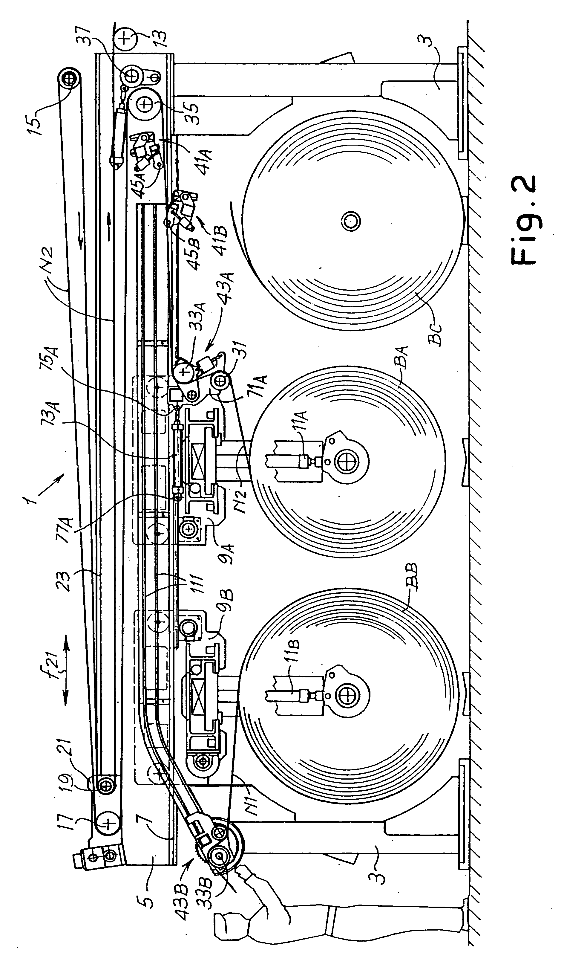
[0026] FIGS. 2 to 5 show in different operating positions an unwinder to feed a web material to a processing line downstream, not shown. A splicing device according to the invention is combined with the unwinder.

[0027] The unwinder illustrated is particularly suitable to feed sheets or webs of cardboard to produce corrugated cardboard. The structure of the unwinder, indicated as a whole with 1, may be different from that show in the figures, the splicing device of the invention also being suitable for application in unwinders differing in arrangement.

[0028] In the example illustrated, the unwinder has a fixed structure with two pairs of uprights 3 (a single upright of each pair being visible in the drawing) and a pair of crosspieces 5 (of which one is visible in the drawing while the other is disposed behind it). The crosspieces 5 carry guides 7 for a pair of carriages or slides 9A and 9B. Each carriage 9A, 9B has engaging and lifting means 11A and 11B to engage and lift or lower re...


PUM

PropertyMeasurementUnit
rotationaaaaaaaaaa
pressureaaaaaaaaaa
counter-pressureaaaaaaaaaa

Abstract

The splicing device comprises two heads (41A, 43A; 41B, 43B), each of which has: a roller (33A; 33B) associated with a clamping bar (93A; 93B) to hold between said roller and said clamping bar an initial edge (L) of the second web material; a counter-pressure member (53A; 53B) cooperating with said roller to press said first and second web materials against each other; and a cutting member (67A; 67B).

Description

[0001] The present invention relates to a device to splice two webs together, for example two sheets of cardboard, to allow continuous feed of a web material wound in reels towards a processing line, for example a machine to produce corrugated cardboard.[0002] The invention also relates to an unwinding device in which reels of web material are unwound in succession, equipped with a splicing device to splice a first web material coming from a reel being unwound to the head or leading edge of a second web material coming from a standing by reel.STATE OF THE ART[0003] In many industrial applications, for example although not exclusively in the production of corrugated cardboard, a web material coming from a reel being unwound is fed towards a production line. In the case of corrugated cardboard, for example, the web material is fed to a so-called "single-facer" or to a so-called "double-facer" to be combined with other sheets of web material, if necessary after corrugation of the mater...

Claims


Application Information

Patent Timeline
Patent Type & Authority Applications(United States)
IPC IPC(8): B65H19/18
CPCB65H19/1836B65H2301/46172B65H2301/4621B65H2701/1762B65H2301/4641B65H2301/46412B65H2408/2211B65H2301/46312
Inventor ADAMI, MAURO
Owner FOSBER
Why Eureka
Try Eureka