RF module and mode converting structure and method

a technology of converting structure and mode, applied in the direction of waveguides, electrical devices, multiple-port networks, etc., can solve the problem that the structure of connecting different waveguides has not been developed sufficiently

Active Publication Date: 2004-05-06
TDK CORPARATION
View PDF4 Cites 202 Cited by
  • Summary
  • Abstract
  • Description
  • Claims
  • Application Information

AI Technical Summary

Problems solved by technology

On the other hand, the waveguide having the multilayer structure is a relatively new technique, and the structure of connecting different waveguides has not been developed sufficiently.

Method used


Image

  • RF module and mode converting structure and method
  • RF module and mode converting structure and method
  • RF module and mode converting structure and method

Examples


first modification

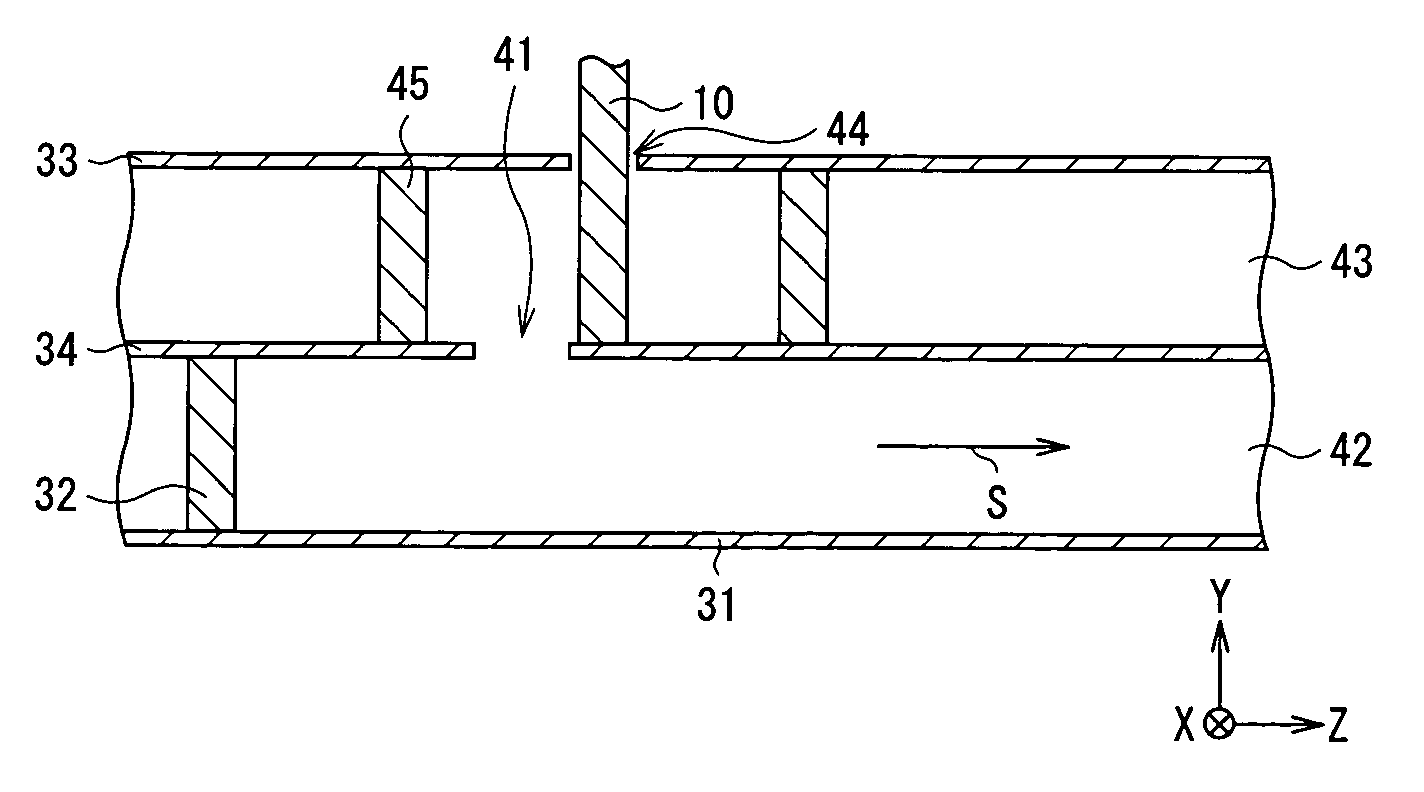
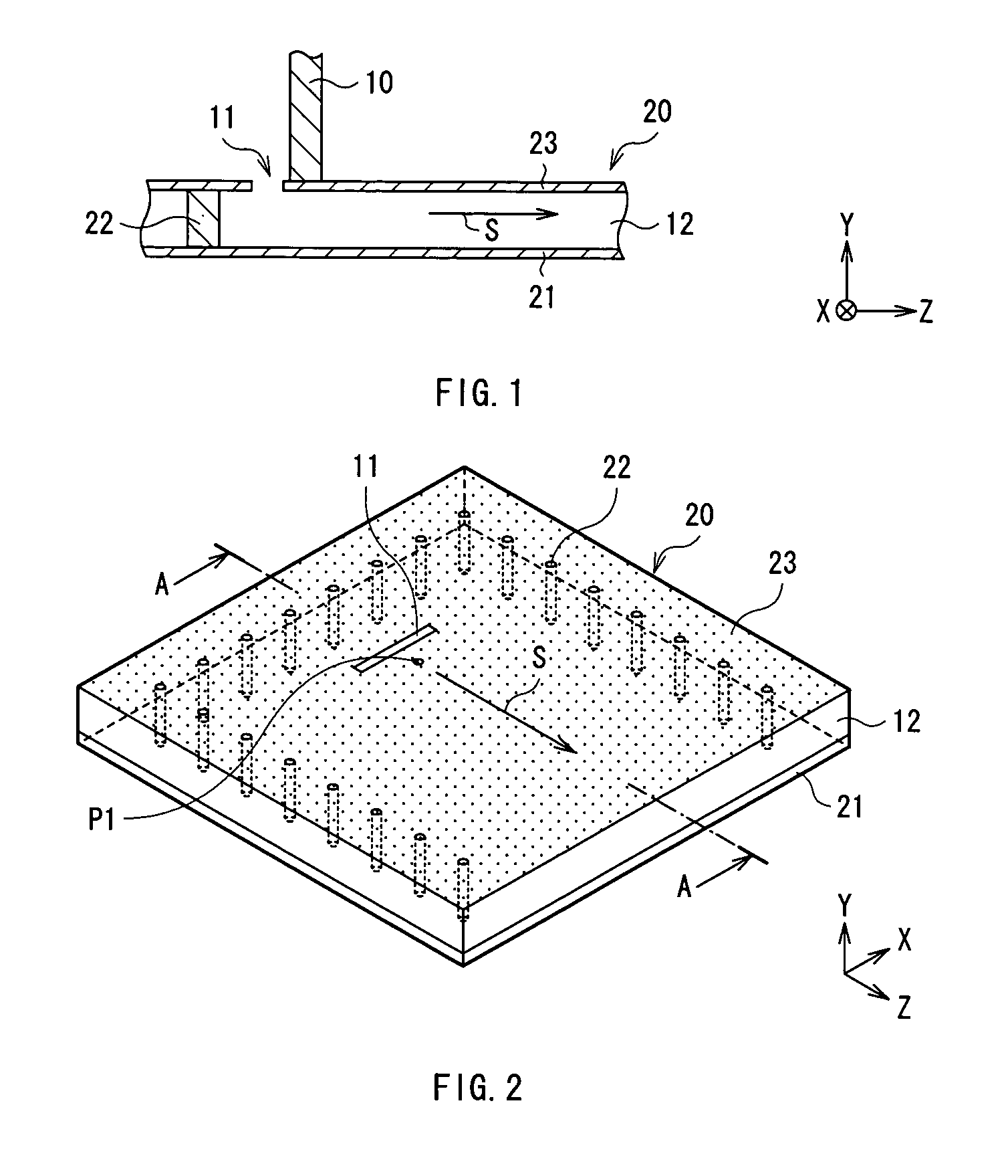
[0073] FIG. 11 shows the configuration of an RF module in a first modification. FIG. 12 is a plan view of the RF module. In FIG. 11, for simplicity of the drawing, the thickness of the uppermost layer is omitted and hatched. In the first modification, a waveguide 90 in a multiple mode (double mode) is used as the second waveguide. In the configuration example, the TEM waveguide 10 is connected to an input / output portion of the waveguide 90 in the double mode.

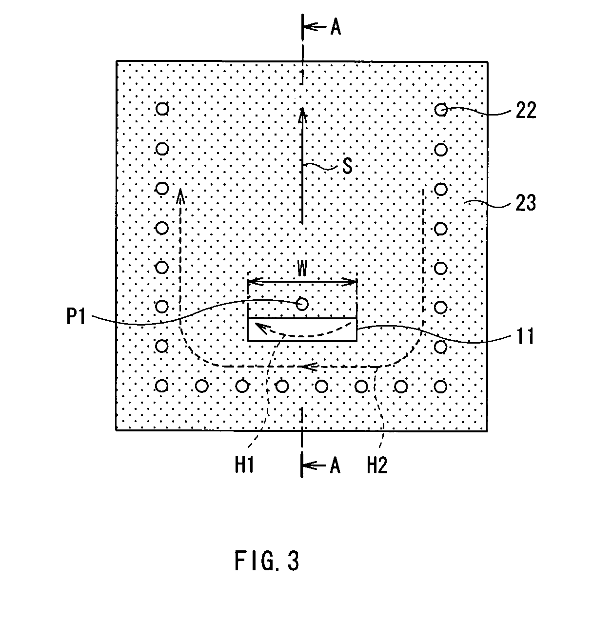
[0074] The waveguide 90 has a dielectric substrate 72, ground electrodes 91 and 93 facing each other, and a plurality of through holes 92 as conductors for bringing the ground electrodes 91 and 93 into conduction. In a region surrounded by the ground electrodes 91 and 93 and the through holes 92, for example, electromagnetic waves propagate in two modes in the directions S1 and S2 in the diagram. The through holes 92 are arranged in, for example, an almost square shape as a whole.

[0075] A structure of connecting the TEM waveguid...

second modification

[0080] FIGS. 15 to 17 show the configuration of an RF module according to a second modification. In FIG. 15, to simplify the drawing, the thickness of an intermediate layer is omitted and hatched. FIG. 17 corresponds to a section taken along line C-C of FIG. 15.

[0081] The RF module of each of the configuration examples has only one electromagnetic wave propagation region on the second waveguide side. In the modification, a waveguide 60 having a multilayer structure as the second waveguide has a plurality of electromagnetic wave propagation regions.

[0082] The waveguide 60 has two dielectric substrates 52 and 53, three ground electrodes 61, 63, and 64 provided on the dielectric substrates 52 and 53 so as to face each other, and a plurality of through holes 55 and 62 as conductors each for bringing at least two ground electrodes of the ground electrodes 61, 63, and 64 into conduction. The lower ground electrode 61 is uniformly provided on the bottom face of the lower dielectric substra...


PUM


Abstract

The present invention is directed to enable mode conversion between a TEM mode and another mode to be performed among a plurality of waveguides. An RF module comprises: a TEM waveguide as a first waveguide for propagating electromagnetic waves in a TEM mode; and a waveguide having a multilayer structure as a second waveguide connected to the first waveguide, for propagating electromagnetic waves in another mode different from the TEM mode. An end of the first waveguide is directly conductively connected to one of ground electrodes of the second waveguide from the stacking direction side of the ground electrodes. Since magnetic fields are coupled so that the direction of the magnetic field of the first waveguide and that of the magnetic field of the second waveguide match with each other in the H plane, mode conversion between the TEM mode and another mode can be excellently performed between the waveguides.

Description

[0001] 1. Field of the Invention[0002] The present invention relates to an RF module used for propagating a signal in a high frequency band of microwaves, millimeter waves, or the like and a mode converting structure and method for converting a mode between different waveguides.[0003] 2. Description of the Related Art[0004] Conventionally, as transmission lines for transmitting a high frequency signal in a microwave band, a millimeter wave band, and the like, a strip line, a microstrip line, a coaxial line, a waveguide, a dielectric waveguide, and the like are known. Each of them is also known as a component of a resonator and a filter for high frequency. An example of a module formed by using any of the components for high frequency is an MMIC (Monolithic Microwave IC). Hereinbelow, a transmission line for high frequency, and a microstrip line, a waveguide, or the like each serving as a component of a filter or the like will be generically called waveguides.[0005] Propagation modes...

Claims


Application Information

Patent Timeline
Patent Type & Authority Applications(United States)
IPC IPC(8): H01P5/107
CPCH01P5/107H01P3/121
Inventor FUKUNAGA, TATSUYA
Owner TDK CORPARATION
Why Eureka
Try Eureka