
Standardized RF module insert for a portable electronic processing device

a technology of electronic processing device and module insert, which is applied in the direction of coupling device connection, electrical apparatus casing/cabinet/drawer, instruments, etc., can solve the problems of signal degradation and attenuation, unsatisfactory solution that places the rf antenna in close proximity to the motherboard and microprocessor of the computer, and adversely affected

Inactive Publication Date: 2005-03-22
HEWLETT PACKARD DEV CO LP
View PDF27 Cites 61 Cited by
  • Summary
  • Abstract
  • Description
  • Claims
  • Application Information

AI Technical Summary

Benefits of technology

The wireless network adapter, as disclosed herein, may advantageously provide a compact, inexpensive solution for enabling wireless communications between electronic devices. The adapter is standardized for assembly as a complete unit across product lines and the configuration of the adapter allows for optimal placement with regards to RF signal reception and transmission.

Problems solved by technology

This communication link is typically established via cumbersome cabling and often proprietary connectors.
IR communication may offer greater security than RF communication, but also requires a direct “line of sight” link between the communicating devices and can be adversely affected by environmental influences.
Unfortunately, these solutions also occupy existing expansion slots that could otherwise be used for peripherals such as network cards and video drivers.
Furthermore, any solution that places the RF antenna in close proximity to a computer's motherboard and microprocessor is less than ideal.
The computer processor and chipset generate noise which results in signal degradation and attenuation.
In devices where the antenna is mounted directly to the communicating device, the antenna usually extends beyond the envelope of the product in which they are installed and may be prone to damage resulting in expensive replacement costs.
In cases like this, the antenna must be connected via a coaxial cable or shielded wire assembly to the main radio circuitry, which adds to the cost and introduces signal loss and degradation.
In addition to being unsightly, the cable assembly can be a nuisance and become tangled with other wiring or other equipment or suffer damage if routed through moving components such as notebook lid hinges.
Another disadvantage of certain existing designs is that as wireless specifications change, radio circuitry may become obsolete.

Method used


Image

  • Standardized RF module insert for a portable electronic processing device
  • Standardized RF module insert for a portable electronic processing device
  • Standardized RF module insert for a portable electronic processing device

Examples


Embodiment Construction

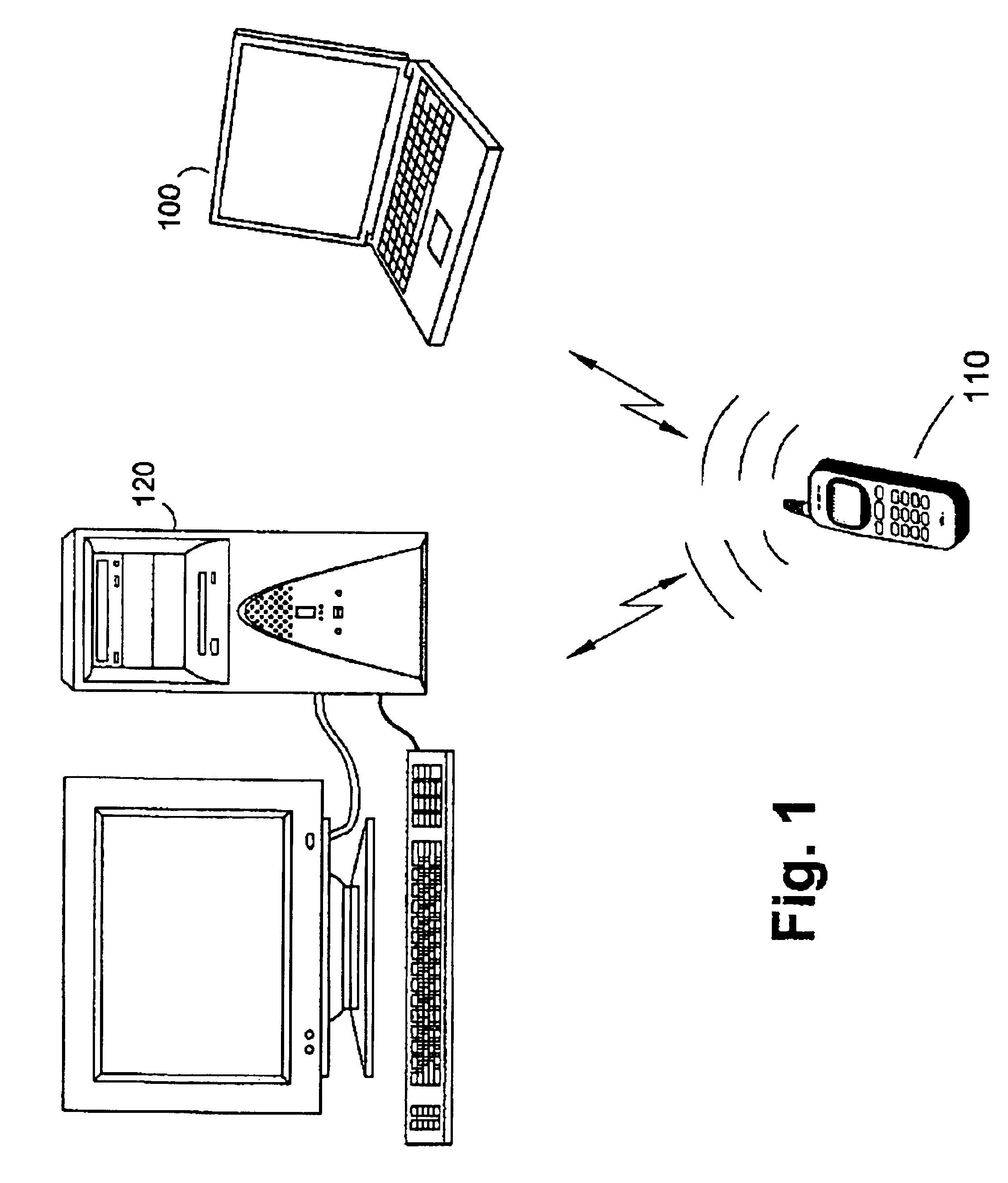
FIG. 1 shows an example of a wireless computer network representing a preferred embodiment of the invention, in which a portable computer 100, a cellular phone 110 and a desktop computer 120 may communicate and / or transfer data to one another via wireless communication links. The communication network may be a Bluetooth personal area network, a “HomeRF” network, a wireless local area network per IEEE 802.11 or any other suitable wireless network. It should be appreciated that a variety of devices may reside and communicate in the network in addition to the devices shown in FIG. 1. These other devices may include facsimile machines, keyboards, joysticks, headsets and any other electronic device whose operation may benefit from a wireless network.

In order to communicate with other devices, each unit must incorporate an RF (and / or an IR) transceiver that is capable of transmitting and receiving signals per the appropriate communication standard. Naturally, each device in the network mu...


PUM


Abstract

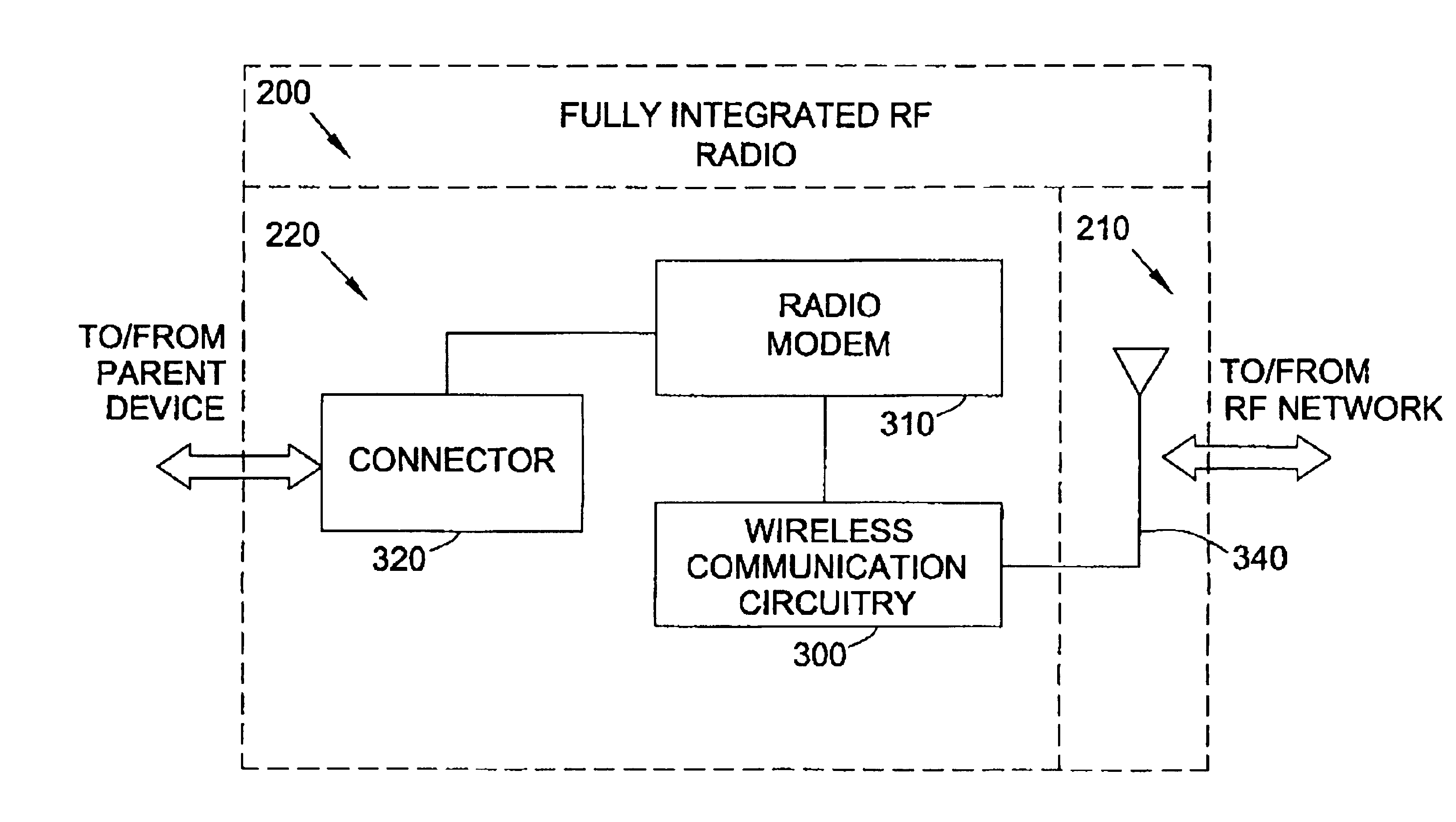
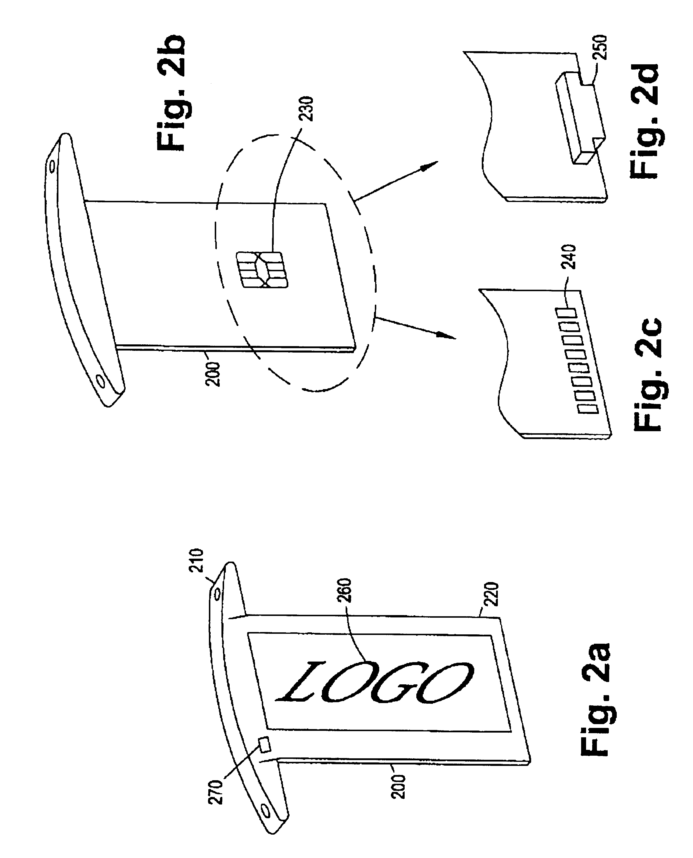
A wireless network adapter for establishing wireless communication links between electronic devices. In one embodiment, the wireless network adapter comprises wireless communication circuitry encased in a shell in the form of a detachable molding element of an electronic device. The wireless network adapter further comprises a bus connector adapted to couple the wireless communication circuitry to an expansion bus when the shell is attached to an outer surface of an electronic device. The wireless network adapter is a fully integrated solution further comprising an RF antenna for communication with a wireless network and a radio modem comprising a radio, a receiver, and modulation circuitry. The RF antenna in the wireless network adapter may take one of several forms. The antenna may be a dedicated unit housed within the shell of the wireless network adapter. Alternatively, the antenna may form a part of the outer shell of the adapter or it may form a part of a company logo located on the shell the adapter. The wireless network adapter is installed in an electronic device such as a portable computer. The electronic device comprises, at a minimum, a system microprocessor, an expansion bus, a read-writeable memory device, an input / output device, and an expansion port connected to the expansion bus that is configured to accept the detachable wireless network adapter. Another embodiment of the present invention comprises an electronic device equipped with an external sleeve configured to accept a wireless network adapter insert.

Description

STATEMENT REGARDING FEDERALLY SPONSORED RESEARCH OR DEVELOPMENTNot applicable.BACKGROUND OF THE INVENTION1. Field of the InventionThe present invention relates generally to a technique for incorporating an RF transceiver onto the body of an electronic device. More particularly, it relates to a fully integrated, device-independent RF transmit / receive module that combines the antenna and associated electronics into a single package and can be installed and used on a variety of electronic devices for the purpose of communicating with other electronic devices.2. Background of the InventionAs portable devices become more capable of storing and displaying information, a need inherently arises for data transfers between these devices. One example of this type of transfer includes the downloading of personal schedules and contact information from a computer to a personal digital (or data) assistant (PDA). This communication link is typically established via cumbersome cabling and often prop...

Claims


Application Information

Patent Timeline
IPC IPC(8): G06F1/16H04M1/725H04M1/72H04L12/28H04M1/72412
CPCG06F1/1616G06F1/1632G06F1/1656G06K19/07741H01Q1/2258H04M1/0254H01Q1/44H04M1/7253H01Q1/2283H04W4/18H04W76/02H04W88/02H04W76/10H04M1/72412
Inventor CASTELL, ROBIN T.CROSSWY, WILLIAM CALDWELL
Owner HEWLETT PACKARD DEV CO LP
Learn More