Semiconductor device with improved design freedom of external terminal

a technology of external terminals and semiconductors, applied in semiconductor devices, semiconductor/solid-state device details, electrical apparatus, etc., can solve the problems of difficult to form 300 external terminals on the surface area of a 7 mm.times.7 mm wcsp, and severely restricted design freedom

Inactive Publication Date: 2004-05-13
LAPIS SEMICON CO LTD
View PDF5 Cites 21 Cited by
  • Summary
  • Abstract
  • Description
  • Claims
  • Application Information

AI Technical Summary

Problems solved by technology

As shall be described below, however, design freedom is severely restricted by the disposal pitch and disposal positions of external terminals.
However, it is extremely difficult to form 300 external terminals on the surface area of a 7 mm.times.7 mm WCSP.
Since both of these connection methods utilize a substrate, an...

Method used


Image

  • Semiconductor device with improved design freedom of external terminal
  • Semiconductor device with improved design freedom of external terminal
  • Semiconductor device with improved design freedom of external terminal

Examples


first embodiment

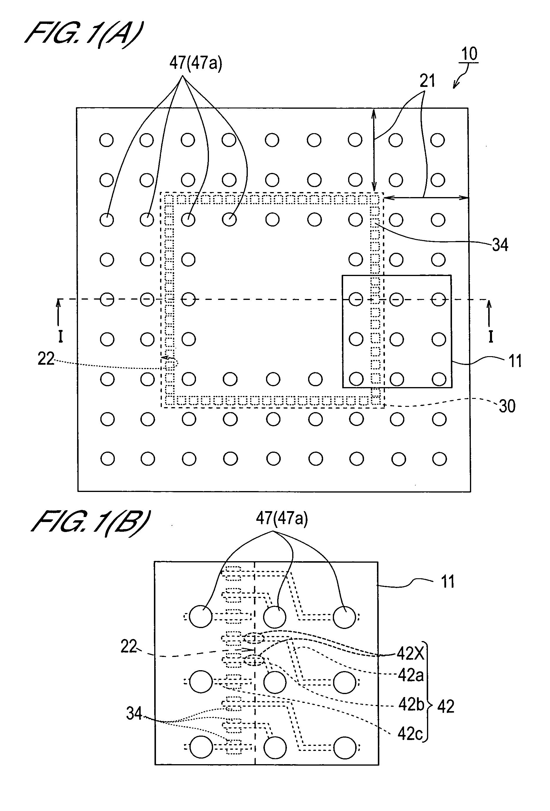
[0153] Next, a modified example of the semiconductor device of the first embodiment will be described with reference to FIG. 3. Note that the plan view seen from above of this example is substantially identical to FIG. 1(A), and hence diagrammatic representation and detailed description thereof have been omitted.

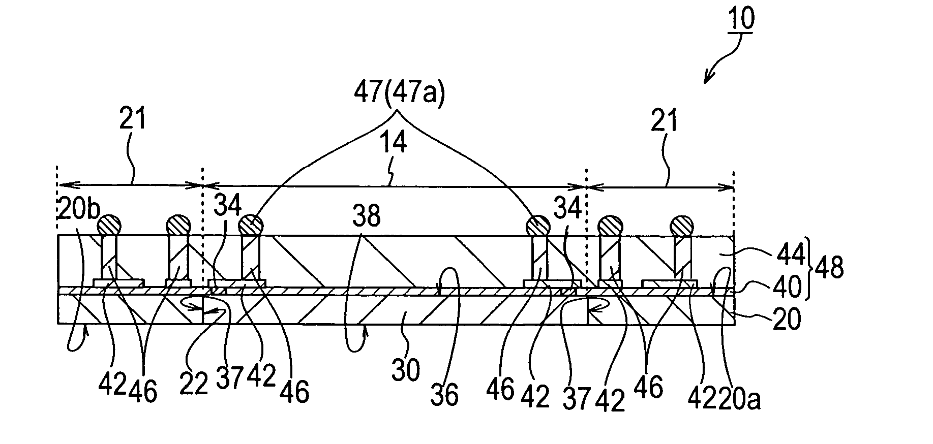
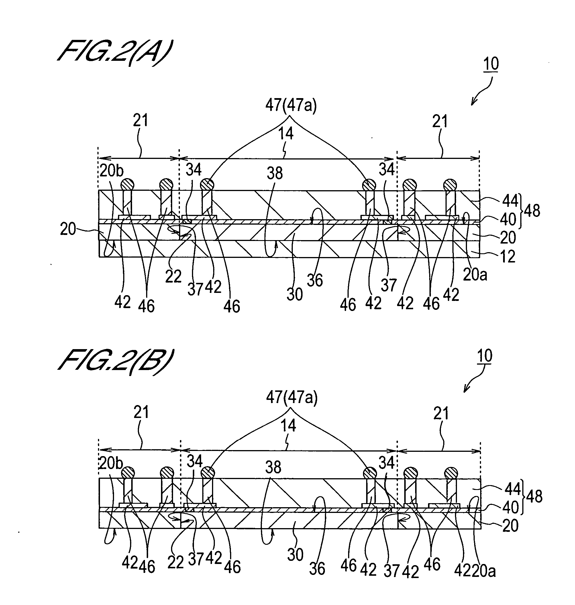
[0154] FIGS. 3(A) and 3(B) are schematic sectional views of a semiconductor device 10' of the modified example and correspond to FIGS. 2(A) and 2(B) respectively. FIG. 3(A) shows a constitutional example in which the semiconductor device 10' is provided with the lower base 12 on its bottom surface. FIG. 3(B) shows a constitutional example in which the lower base 12 is not provided.

[0155] The semiconductor 10' of this modified example differs in the form of peripheral inside walls 24 which define the opening portion 22 of the base frame 20. Accordingly, other similar constitutional components to the first embodiment are allocated and illustrated with identical reference symbo...

second embodiment

[0228] Second Embodiment

[0229] A semiconductor device according to a second embodiment of this invention will now be described with reference to FIGS. 14(A), 14 (B), and 15(A). Note that since the plan views seen from above in the description of the second embodiment are substantially identical to the plan views already described in the first embodiment, description thereof has been omitted and the second embodiment will be described using sectional views only. Further, applied materials, process implementation conditions, and so on are similar to those of the first embodiment, and hence detailed description thereof has also been omitted.

[0230] FIG. 14(A) is a schematic plan view showing the constitution of the semiconductor device of the second embodiment, and FIG. 14(B) is a plan view showing an expanded outline of the main parts of the region in 14(A) which is surrounded by a solid line 11 in order to illustrate the connection relationship between a wiring pattern, electrode pads...


PUM


Abstract

A semiconductor device comprises a base frame having a first surface and a second surface which opposes the first surface, and having an opening portion a semiconductor chip 30 which includes a first main surface on which a plurality of electrode pads is provided and a second main surface, and which is disposed within the opening portion; an insulating film formed on the first surface and first main surface; a plurality of wiring patterns which extend from the electrode pads, respectively to the upper side of the first surface of the base frame, respectively; a sealing portion formed on the wiring patterns and insulating film; and a plurality of external terminals provided on the wiring patterns in a region including the upper side of the base frame.

Description

[0001] 1. Field of the Invention[0002] This invention relates to a semiconductor device, and more particularly to a semiconductor device in which the degree of design freedom of an external terminal is increased in accordance with further increases in the number of external terminals.[0003] 2. Description of Related Art[0004] Demands have been made in recent years for further reductions in the size and thickness of packaged semiconductor devices. In response to such demands, a packaging form known as a Wafer Level Chip Size Package (to be referred to simply as WCSP hereinafter), in which the external size of the packaging is substantially equal to the external size of the semiconductor chip, has been proposed.[0005] A WCSP comprises a semiconductor chip. The semiconductor chip comprises a circuit element having a predetermined function and a plurality of electrode pads electrically connected to each other on the circuit element. An insulating film is formed on the surface of the sem...

Claims


Application Information

Patent Timeline
IPC IPC(8): H01L23/12H01L23/538
CPCH01L23/5389H01L24/19H01L24/11H01L2224/12105H01L2224/32145H01L2224/73267H01L2924/351H01L2924/15787H01L2924/12042H01L2224/05008H01L2224/05026H01L2224/05001H01L2224/05569H01L2224/06135H01L24/05H01L2924/00H01L2224/05611H01L2924/00014H01L2224/05644H01L2224/05647H01L2224/05655H01L2224/05124H01L2224/05147
Inventor SHIZUNO, YOSHINORI
Owner LAPIS SEMICON CO LTD
Why Eureka
Try Eureka