Loss point detecting method and distributed Raman amplifier applying the same
a technology of loss point and amplifier, applied in the direction of electromagnetic repeaters, transmission monitoring, instruments, etc., can solve the problems of optical transmission path material burning out at the loss point, insufficient gain,
- Summary
- Abstract
- Description
- Claims
- Application Information
AI Technical Summary
Benefits of technology
Problems solved by technology
Method used
Image
Examples
first embodiment
[0039] When an excitation light is applied to an optical fiber transmission path, a scattered light and a reflected light occur other than a signal light thus amplified, as shown in FIG. 4. And when a loss point occurs in the optical fiber transmission path as mentioned above, the scattered light power ASS is small while the reflected light power Pm is large. When no loss point occurs, contrary, the scattered light power is large while the reflected light power is small. Accordingly, the present invention performs control of the excitation light power by monitoring the scattered light power and the reflected light power, and then based on the thus-monitored powers.
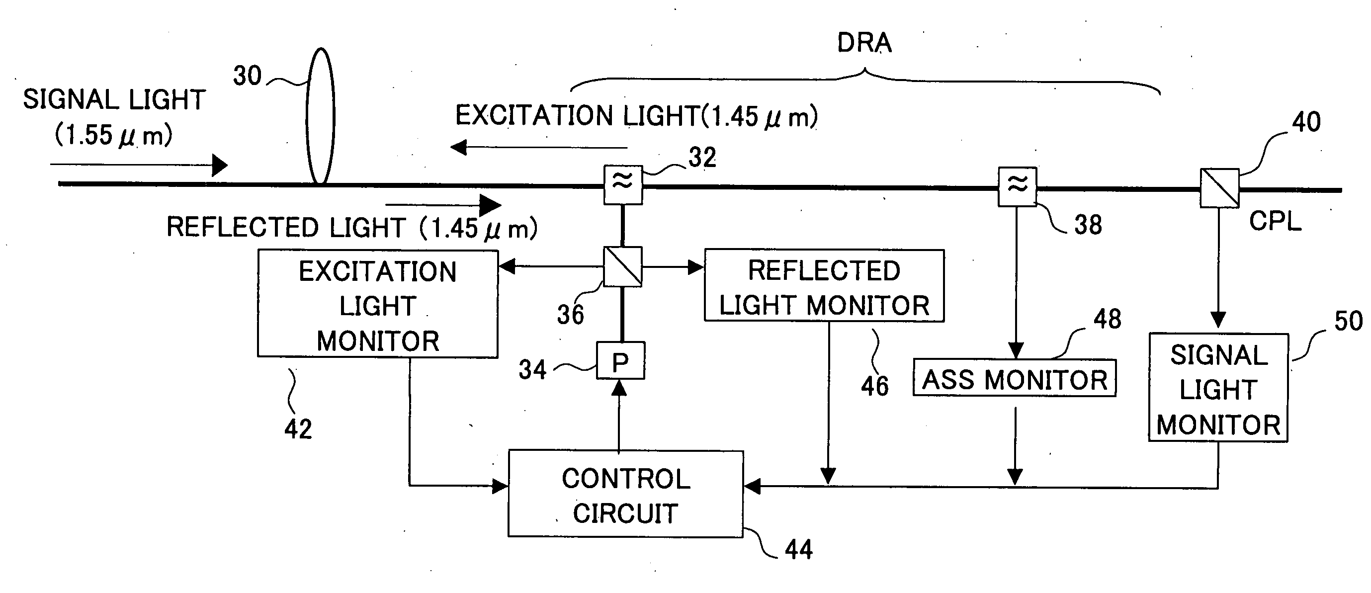
[0040] FIG. 5 shows a block diagram of a distributed Raman amplifier in the first embodiment of the present invention. As shown, a signal light for example with the wavelength of 1.55 .mu.m is transmitted through an optical fiber 30 which is an optical transmission path. This signal light is applied to a band separation op...
second embodiment
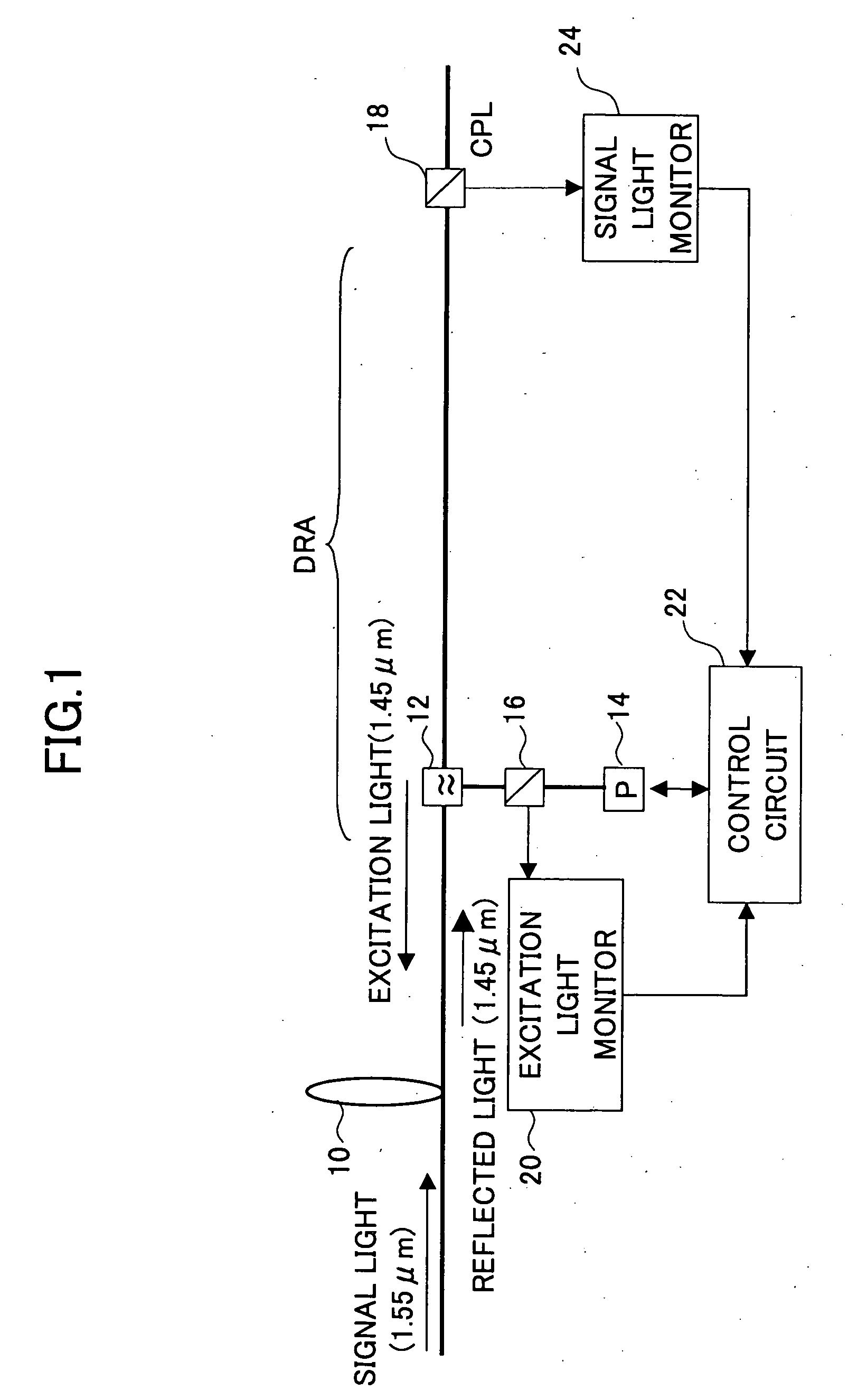
[0054] FIG. 11 shows a block diagram of a distributed Raman amplifier according to the present invention. In the figure, the same reference numeral is given to the same portion as that in FIG. 5. A point different from FIG. 5 is that a band separation optical coupler 39 is provided instead of the band separation optical coupler 38, in FIG. 11. In FIG. 11, through an optical fiber 30 which is an optical transmission path, a signal light for example with the wavelength of 1.55 .mu.m is transmitted. This signal light is applied to the band separation optical coupler 32. An excitation light with the wavelength of 1.45 .mu.m is supplied also to the band separation optical coupler 32 through an optical coupler 36 from an excitation light source 34, and, is applied, in a direction opposite to the transmission direction of the signal light, to the an optical fiber 30 with the band separation optical coupler 32.
[0055] Thereby, the signal light is amplified by using the optical fiber 30 as an...
third embodiment
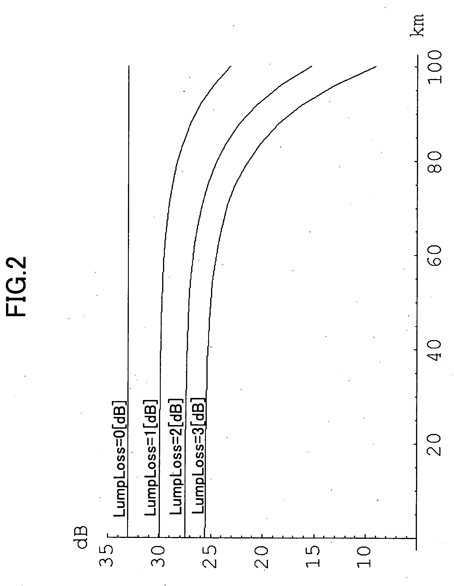
[0059] A control manner according to the present invention in which the excitation light power control is performed not monitoring the reflected light power but monitoring the scattered light power will now be described. When a loss point exists in an optical transmission path, the scattered light power ASS is small. On the other hand, the scattered light power ASS is large when there is no loss point. By utilizing this behavior, the control is made referring to a relation between the excitation light power P and the scattered light power ASS.
[0060] FIG. 12 shows a relation of the scattered light power ASS with respect to the excitation light power P in case of setting the length of the optical fiber transmission path as 100 [km] and the loss at a loss point as 1 [dB]. The five curves shown in the figure show the relations in case the loss point is located at a position of 0 [km], 90 [km], 95 [km], 99 [km], and 100 [km] from the point at which the excitation light is applied, respec...
PUM
| Property | Measurement | Unit |
|---|---|---|
| wavelength | aaaaa | aaaaa |
| wavelength | aaaaa | aaaaa |
| length | aaaaa | aaaaa |
Abstract
Description
Claims
Application Information
 - R&D
- Intellectual Property
- Life Sciences
- Materials
- Tech Scout
- Unparalleled Data Quality
- Higher Quality Content
- 60% Fewer Hallucinations
Browse by: Latest US Patents, China's latest patents, Technical Efficacy Thesaurus, Application Domain, Technology Topic, Popular Technical Reports.
© 2025 PatSnap. All rights reserved.Legal|Privacy policy|Modern Slavery Act Transparency Statement|Sitemap|About US| Contact US: help@patsnap.com


