Accumulation type fuel injection system

a fuel injection system and accumulation type technology, applied in the direction of liquid fuel feeders, machines/engines, electric control, etc., can solve the problems of noise generation in combustion, supply pump no function to actively and supply pump has no function to reduce the pressure of common rail

Active Publication Date: 2004-05-27
DENSO CORP
View PDF2 Cites 18 Cited by
  • Summary
  • Abstract
  • Description
  • Claims
  • Application Information

AI Technical Summary

Benefits of technology

[0016] According to an aspect of the present invention, an accumulation type fuel injection system slackens combustion by controlling fuel injection performed by an injector when high-temperature combustion is predicted by high-temperature combustion predicting means. Thus, noise generated by the high-temperature combustion can be alleviated.
[0017] More specifically, the noise, which is caused by the high-temperature combustion when an actual common rail pressure is higher than a target pressure suitable for an operating state, can be alleviated without causing an increase in a number of parts or degradation of mounting performance due to addition of the pressure reduction valve.

Problems solved by technology

Such noise is generated when a large amount of heat is generated during short-period combustion.
However, the supply pump has no function to reduce the common rail pressure actively.
Thus, the noise is generated in the combustion, in which a large amount of heat is generated in a short period.
The generation of the high-temperature combustion is not preferable for performance of the vehicle, too.
As a result, mounting performance of the common rail to the vehicle is degraded because of the addition of the pressure reduction valve.
Meanwhile, the cost is increased because of the increase in the number of parts or an increase in assembling processes.
As a result, the noise is generated by the high-temperature combustion in an early stage of the pressure reduction.

Method used


Image

  • Accumulation type fuel injection system
  • Accumulation type fuel injection system
  • Accumulation type fuel injection system

Examples


first embodiment

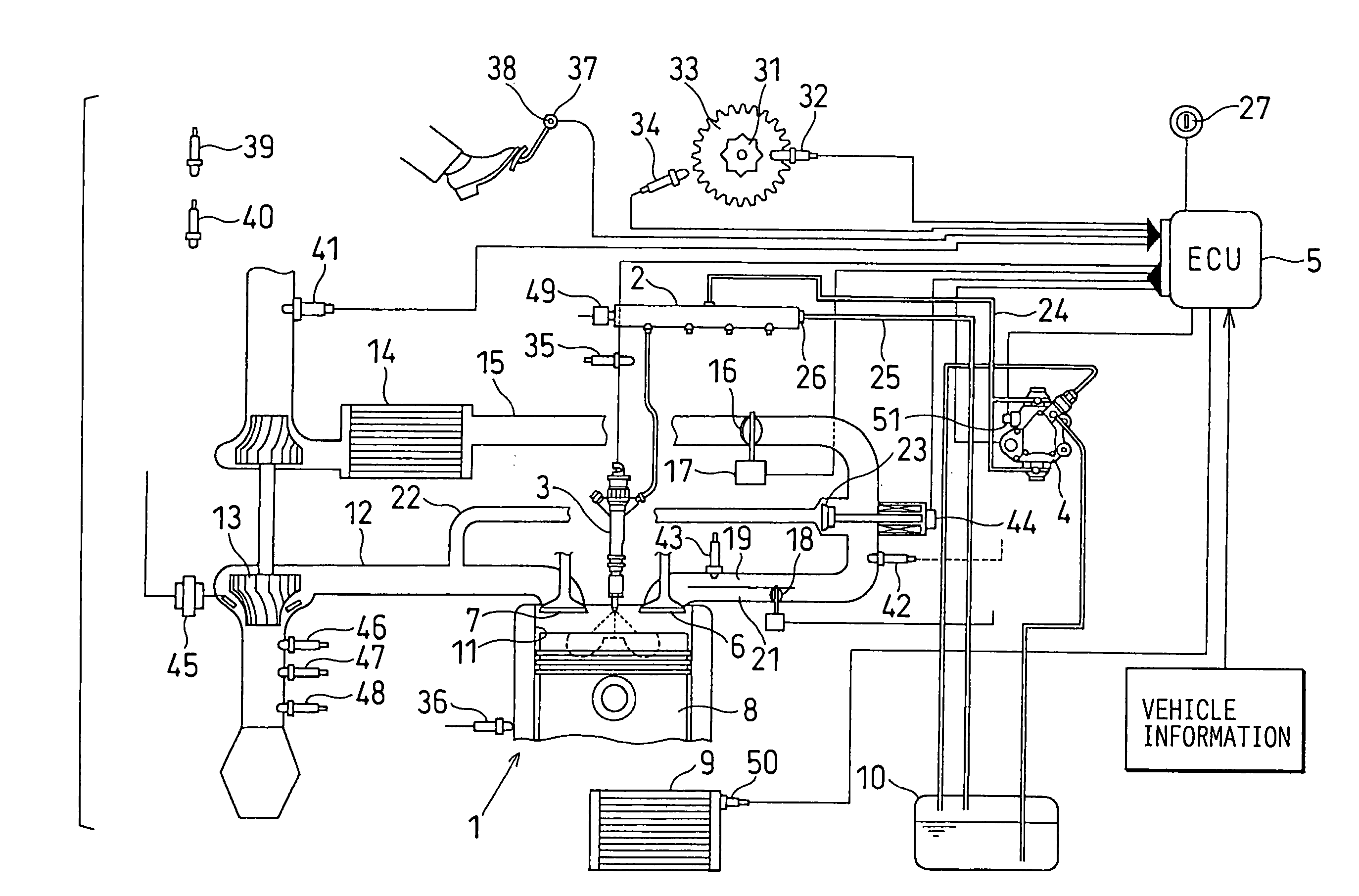
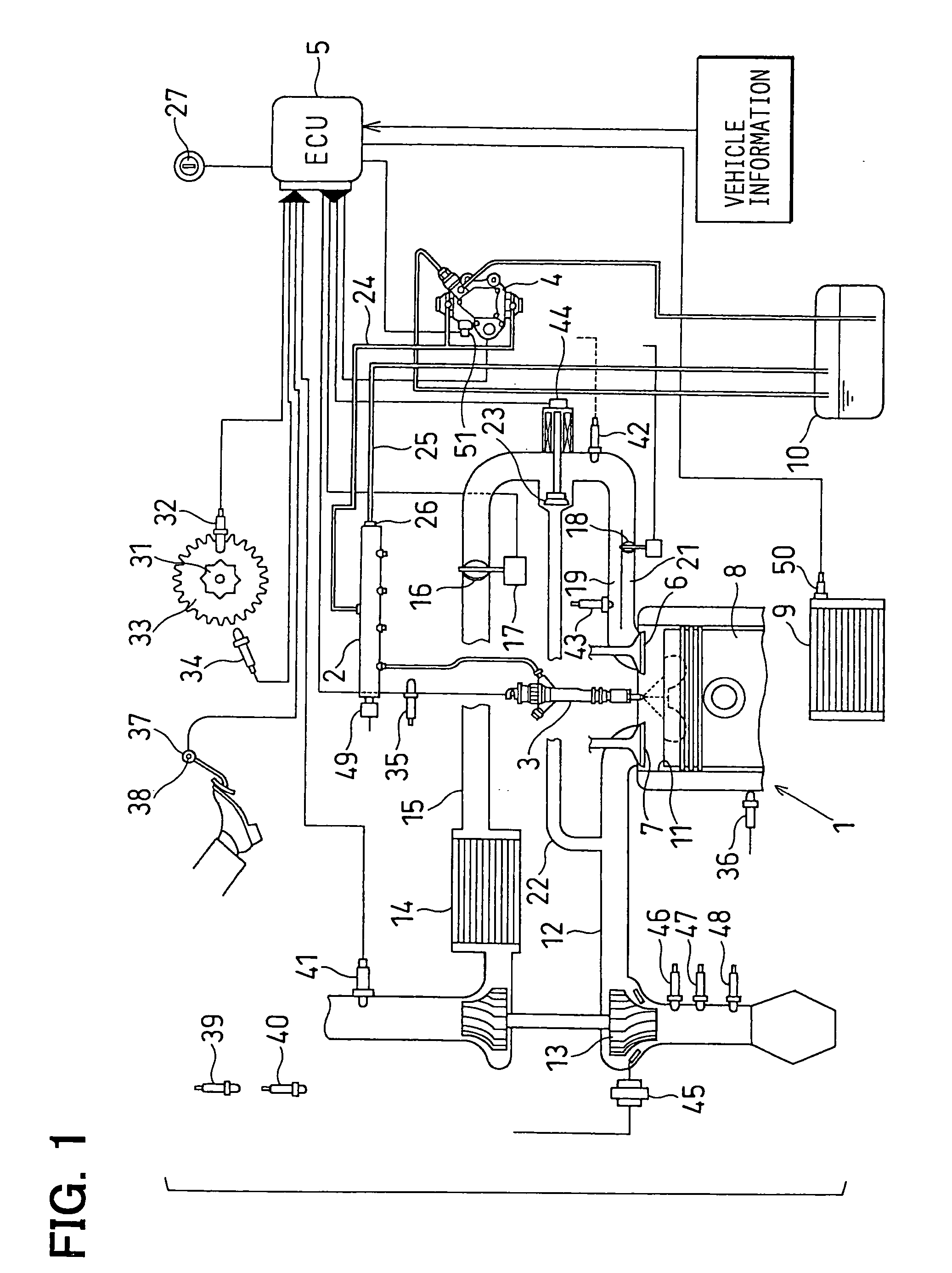
[0032] Referring to FIG. 1, an accumulation type fuel injection system according to the first embodiment of the present invention is illustrated. As shown in FIG. 1, the accumulation type fuel injection system of the present embodiment is a system for injecting fuel into an internal combustion engine (an engine, hereafter) 1 such as a four-cylinder diesel engine. The accumulation type fuel injection system has a common rail 2, injectors 3, a supply pump 4, an engine control unit (ECU) 5, and the like. The common rail 2 is a high-pressure vessel for accumulating the fuel at a high pressure corresponding to a fuel injection pressure. The injectors 3 inject the fuel accumulated in the common rail 2 into respective cylinders of the engine 1. The supply pump 4 pressurizes drawn fuel and pressure-feeds the high-pressure fuel to the common rail 2. The ECU 5 corresponds to a control device for electronically controlling the injectors 3 and the supply pump 4 in accordance with an operating s...

second embodiment

[0087] Next, an accumulation type fuel injection system according to the second embodiment will be explained based on FIGS. 7 and 8.

[0088] Combustion slackening means of the second embodiment slackens the combustion by setting the injection mode to the multi-step injection mode (the pilot injection mode or the multi-injection mode) so that the injection quantity of the minute injection is increased from the injection quantity of the minute injection in the normal injection mode as shown by a solid line Qp1 and a broken line Qp2 in FIG. 7A. The solid line Qp1 in FIG. 7A represents an injection ratio in the normal injection mode. The broken line Qp2 in FIG. 7A represents an injection ratio in the corrected injection mode. The main injection quantity is decreased by the increase in the injection quantity of the minute injection as shown in FIG. 7A.

[0089] The combustion slackening means of the present embodiment increases the injection quantity of the minute injection as the pressure di...

third embodiment

[0096] Next, an accumulation type fuel injection system according to the third embodiment of the present invention will be explained based on FIGS. 9 and 10.

[0097] Combustion slackening means of the third embodiment slackens the combustion by performing the minute injection and the main injection in one injection period through the injector 3 and by lengthening an interval INT between the injections in one injection period as shown by broken lines in FIG. 9A from a normal injection interval shown by solid lines in FIG. 9B.

[0098] The combustion slackening means of the present embodiment lengthens the injection interval INT in one injection period as the pressure difference .DELTA.P provided by subtracting the target pressure Pfin from the actual pressure NPC increases. More specifically, the combustion slackening means calculates a correction coefficient K corresponding to the pressure difference .DELTA.P with a formula or a map and increases the injection interval INT by multiplying...


PUM


Abstract

An electronic control unit of an accumulation type fuel injection system increases a number of injections performed by an injector in one injection period from a normal injection number if a pressure difference provided by subtracting target pressure from actual pressure is greater than a determination threshold and conditions for performing the injection are established, or if high-temperature combustion is predicted. If a normal injection mode is a main injection mode, it is changed to a pilot injection mode or a multi-injection mode. If the normal injection mode is the pilot injection mode, it is changed to the multi-injection mode. If the normal injection mode is the multi-injection mode, a number of minute injections is increased. Thus, combustion is slackened and noise caused by the high-temperature combustion can be alleviated.

Description

[0001] This application is based on and incorporates herein by reference Japanese Patent Application No. 2002-337085 filed on Nov. 20, 2002.[0002] 1. Field of the Invention[0003] The present invention relates to an accumulation type fuel injection system for injecting high-pressure fuel accumulated in a common rail through injectors.[0004] 2. Description of Related Art[0005] An accumulation type fuel injection system calculates an injection quantity of fuel injected from an injector in accordance with an operating state of an engine. For instance, as for a fuel injection quantity during a normal operation, a basic injection quantity is calculated in accordance with an accelerator position and engine rotation speed. Then, a target injection quantity Qfin is calculated by correcting the basic injection quantity in accordance with effects of engine water temperature, a supercharging pressure, the atmospheric pressure, fuel temperature and the like.[0006] As for a pressure in a common r...

Claims


Application Information

Patent Timeline
Patent Type & Authority Applications(United States)
IPC IPC(8): F02M45/08F02B29/04F02B37/00F02D21/08F02D23/02F02D41/22F02D41/38F02D41/40F02D45/00F02M25/07F02M45/02F02M45/04F02M47/00F02M47/02F02M51/00F02M63/00F02M63/02
CPCF02B29/0406Y02T10/123F02B2275/14F02D23/02F02D35/025F02D41/005F02D41/1448F02D41/1454F02D41/187F02D41/3809F02D41/3827F02D41/3845F02D41/402F02D41/403F02D2041/0265F02D2041/1433F02D2200/023F02D2200/0406F02D2200/0414F02D2200/0602F02D2200/0606F02D2200/501F02D2200/602F02D2200/703F02D2250/31F02M25/0707F02M25/0724F02M25/0754F02M25/0755F02M45/02F02M45/04F02M63/0225Y02T10/44F02B37/00F02M26/05F02M26/21F02M26/46F02M26/47Y02T10/12Y02T10/40
Inventor ITO, YOSHIOTAKEUCHI, KATSUHIKO
Owner DENSO CORP
Why Eureka
Try Eureka