Catheter

Active Publication Date: 2004-06-17
ABBOTT LAB VASCULAR ENTERPRISE
View PDF17 Cites 5 Cited by
  • Summary
  • Abstract
  • Description
  • Claims
  • Application Information

AI Technical Summary

Benefits of technology

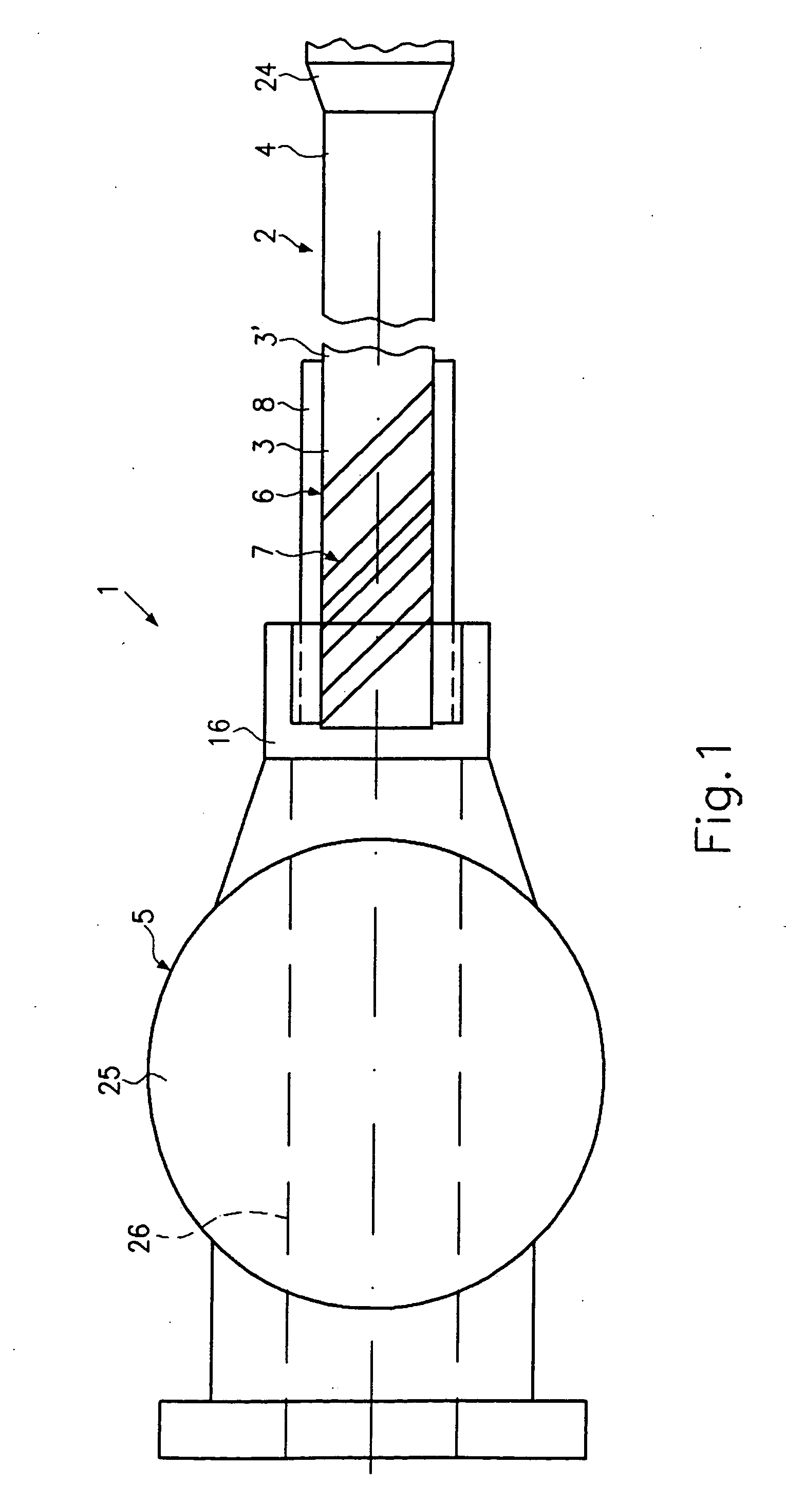
0010] By contrast, the deliberate provision of a bending section at the proximal end of the catheter shaft in accordance with the invention solves the technical problem underlying the invention in a surprisingly simple and unforeseeable way because the deliberate provision of a bending section exactly in the critical region of the catheter shaft that is particularly sensitive to kinking in the generic catheter creates increased flexibility which, although it permits an intended bending, reliably prevents undesired kinking or even breaking because a plastic deformation of the catheter shaft is prevented.
0011] U.S. Pat. No. 6,387,076 discloses a further catheter which has a spiral cut into the hypotube distally of the woven catheter shaft. Said spiral, however, is just meant to improve the flexibility of the catheter shaft in the distally situated region of the catheter. Therefore, according to the above-mentioned U.S. Pat. No. 5,569,200, the spiral cannot prevent the risk of kinking of the catheter behind the fitting.
0012] Furthermore, it is described in U.S. Pat. No. 6,387,076 that for preventing kinking of the catheter behind the fitting the proximal catheter shaft is reinforced with a polymer over a length of about 6 to 12 inches or stabilized by way of reinforcement. Said reinforcement, however, just shifts the point of kinking in distal direction towards the end of the reinforcement. Moreover, the polymer reinforce

Problems solved by technology

The user may kink the catheter shaft when removing the shaft from the packaging and the protective cover or when connecting the pressure device.
Kinking is particularly critical for the reason that it may lead to an occlusion of the inflation lumen, which makes the catheter inoperative.
In this respect the slits cannot solve the above-explained problem because in the generic catheter there is still the risk of kinking or even breaking upon application of external forc

Method used


Image

  • Catheter
  • Catheter
  • Catheter

Examples


Example

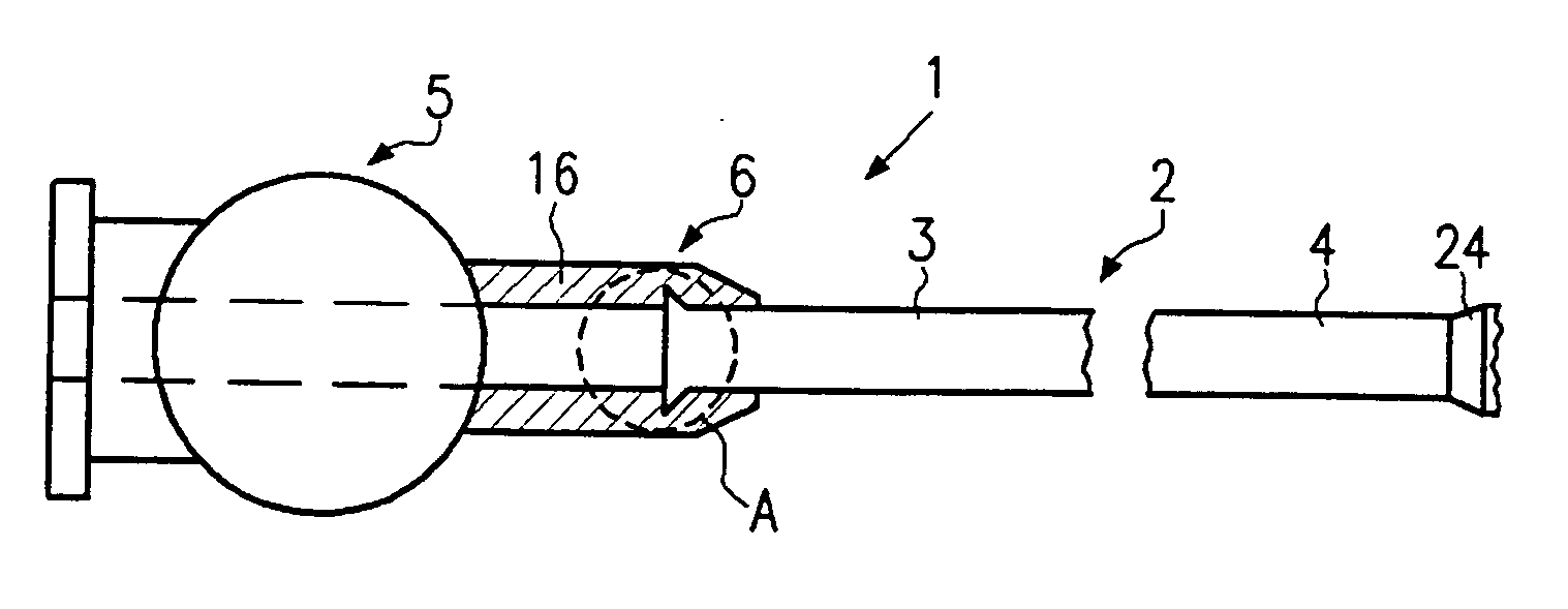
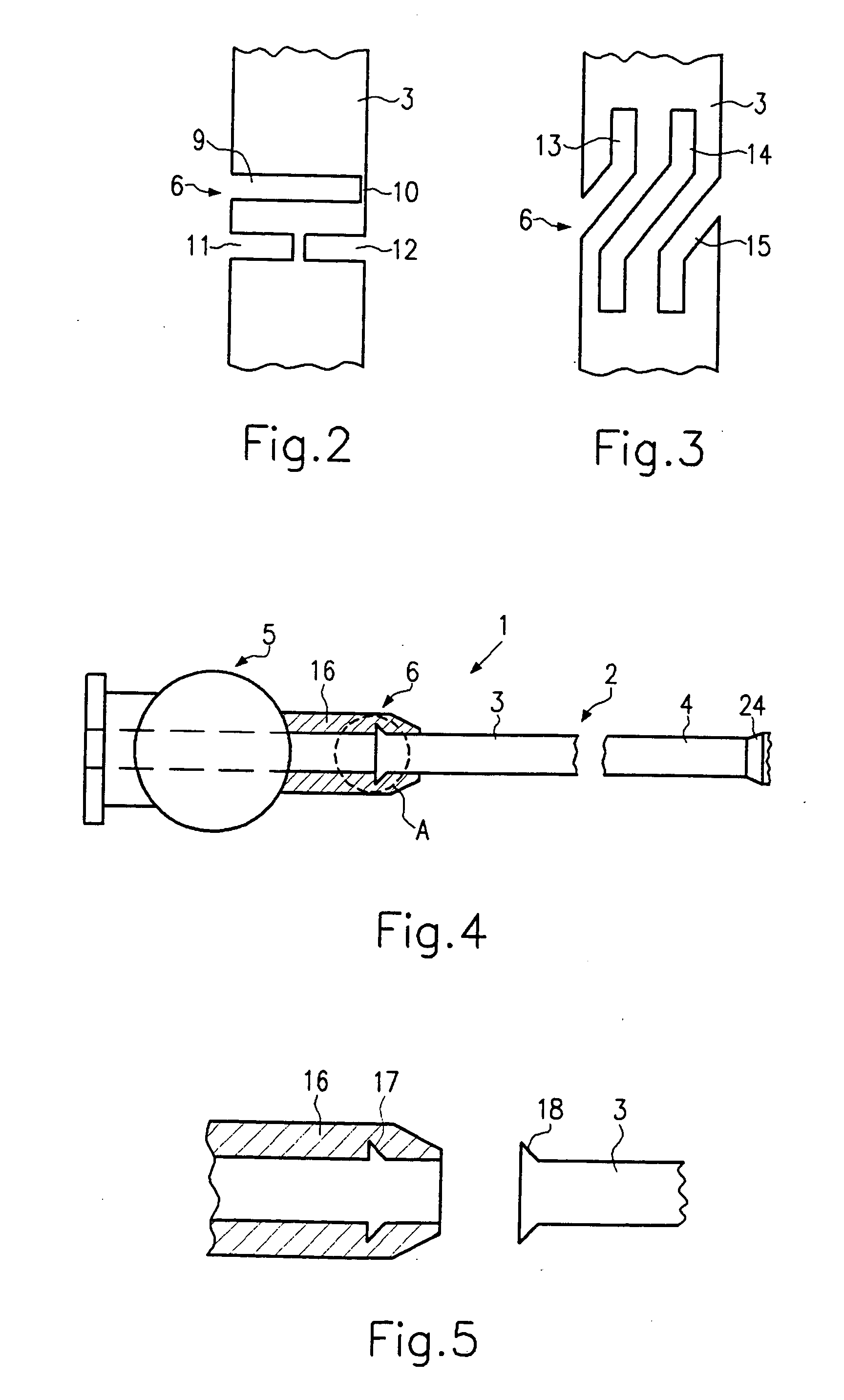
[0037] Referring now to FIGS. 4 and 5, a catheter 1 in accordance with a second embodiment will now be explained. In view of the similarity between the first and second embodiments, the parts of the second embodiment that are identical to the parts of the first embodiment will be given the same reference numerals as the parts of the first embodiment. Moreover, the descriptions of the parts of the second embodiment that are identical to the parts of the first embodiment may be omitted for the sake of brevity. Reference can here be made to the above explanations.

[0038] In the embodiment according to FIG. 4, the transition member 16 is formed as a flexible plastic section of the fitting 5 that is connected to the proximal end 3 of the catheter shaft 2. The detail according to FIG. 5 shows an undercut 17 which can be engaged by a holding member 18 of the proximal end 3 of the catheter shaft 2 for fixing the catheter shaft 2.

Example

THIRD EMBODIMENT

[0039] Referring now to FIG. 6, a catheter 1 in accordance with a third embodiment will now be explained. In view of the similarity between the third and prior embodiments, the parts of the third embodiment that are identical to the parts of the prior embodiments will be given the same reference numerals as the parts of the prior embodiments. Moreover, the descriptions of the parts of the second embodiment that are identical to the parts of the first embodiment may be omitted for the sake of brevity. Reference can here be made to the above explanations.

[0040] In this embodiment, the bending section 6 comprises a plurality of balls 19 to 23 mounted on the proximal end 3. Said balls can be fixed to the catheter shaft 2 by way of different fastening possibilities as have been explained at the outset. In the embodiment shown in FIG. 6, a heat shrinkable tube 27 is provided for this purpose, said tube being connected at one end to the catheter shaft 2 and fixed at the oth...


PUM


Abstract

A catheter is configured to prevent kinking of a catheter during handling or mounting of a pressure device. The catheter has a proximal end of its catheter shaft that is provided with a bending section having a flexibility greater than that of the section of the catheter shaft joining the proximal end.

Description

[0001] 1. Field of the Invention[0002] This invention generally relates to a catheter that is not prone to kinking.[0003] 2. Background Information[0004] A generic catheter is disclosed in U.S. Pat. No. 5,569,200, which basically comprises a catheter shaft that is normally designated as a "hypotube". A fitting, preferably in the form of a luer fitting, is provided at the proximal end of said catheter shaft and serves to connect a pressure device via which pressurized fluid is introduced through channels provided in the fitting so as to expand the balloon at the distal end of the catheter shaft.[0005] In view of the above, there exists a need for an improved catheter which overcomes the above mentioned problems in the prior art. This invention addresses this need in the prior art as well as other needs, which will become apparent to those skilled in the art from this disclosure.[0006] Investigations conducted within the scope of the present invention have shown that the transition po...

Claims


Application Information

Patent Timeline
IPC IPC(8): A61M25/00A61M25/06A61M25/18A61F2/958
CPCA61M25/0606A61M25/0054
Inventor SCHNEIDERHARTWIG, JUDITHNIELSEN, STEVAN
Owner ABBOTT LAB VASCULAR ENTERPRISE
Why Eureka
Try Eureka