
Method for making a multilayer circuit board having embedded passive components

a multi-layer circuit board and passive component technology, applied in the direction of high-frequency circuit adaptation, cross-talk/noise/interference reduction, printed resistor incorporation, etc., can solve the problems of two types of embedded passives commercially available for industrial mass production, embedded capacitors and resistors attached to the same circuit layer have never been achieved in the prior ar

Inactive Publication Date: 2004-07-08
PHOENIX PRECISION TECH CORP
View PDF6 Cites 29 Cited by
  • Summary
  • Abstract
  • Description
  • Claims
  • Application Information

AI Technical Summary

Benefits of technology

"The present invention provides a method for fabricating a core circuit board with embedded passive components, such as resistors, capacitors, and inductors, in a high-density multilayer circuit board. The method simplifies the process of embedding the passive components in a multilayer circuit board and ensures high reliability. The invention also provides a conductive foil with a continuous or non-continuous resistive film on its one side, which can be laminated to a high dielectric layer to form a two-layer core circuit board with embedded passive components. The invention further provides a process of making a core circuit board with at least two capacitors and a method of forming capacitors and resistors in a multilayer circuit board."

Problems solved by technology

Currently, the critical issue is how to integrate the existing thick-film or thin-film passive components into the circuit board, which must be easily adaptable to the manufacturing process of a multilayer circuit board.
In the present time, however, only two types of embedded passives are commercially available for industrial mass production.
However, the embedded capacitors and resistors attached to the same circuit layer have never been achieved in the prior art, which can be accomplished by the method proposed herein of combining the advantages of the fabrication processes which have been taught in the U.S. Pat. Nos. 5,343,320 and 5,870,274.

Method used


Image

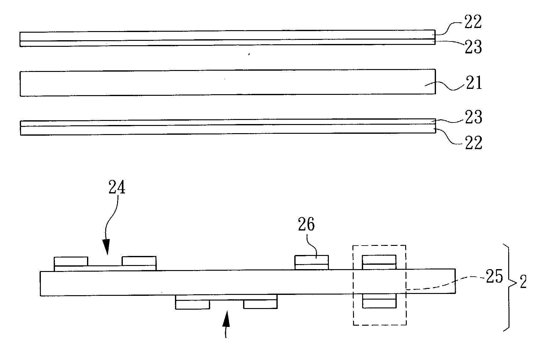
  • Method for making a multilayer circuit board having embedded passive components
  • Method for making a multilayer circuit board having embedded passive components
  • Method for making a multilayer circuit board having embedded passive components

Examples


Embodiment Construction

[0021] For a better understanding on the advantages and capabilities of the present invention, reference is made to the following disclosure, appended claims in connection with the accompanying drawings. It will be obvious to one skilled in the art that the principle feature of the invention may be employed in various embodiments without departing from the scope of the invention.

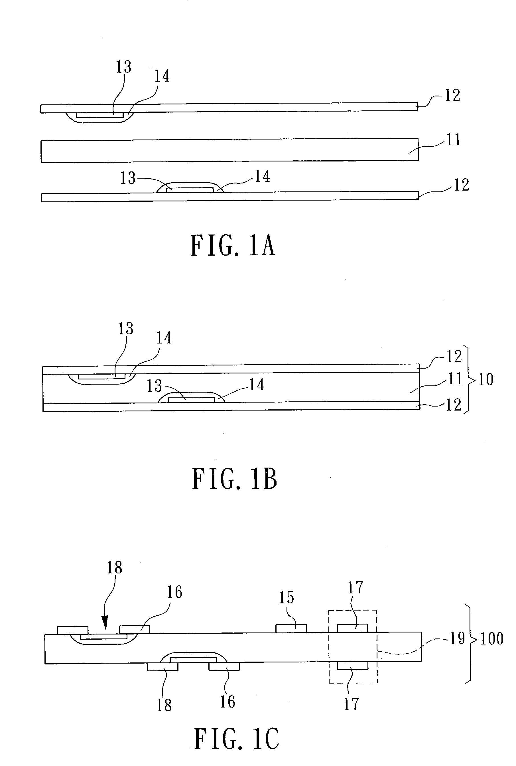
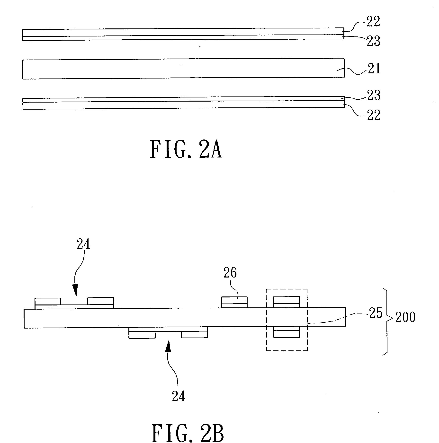
[0022] The invention provides a method to manufacture a high density multilayer circuit board in which embedded capacitive and resistive components are attached to the same circuit layer. In the method, a high dielectric layer is used as an adhesive to further stack two conductive foils which already carry resistive material. Such said high dielectric layer combined with the conductive foils carrying resistive material then introduced into the multilayer circuit board lamination process. After lamination, the circuit pattern and electrodes for the passive components are finally formed on the same conductive ...


PUM

PropertyMeasurementUnit
dielectric constantaaaaaaaaaa
electrically conductiveaaaaaaaaaa
conductiveaaaaaaaaaa

Abstract

A method for fabricating a core circuit board having passive components, such as resistors, capacitors and inductors, is disclosed, which can be used to construct a multilayer circuit board having embedded passive components. In making such as a core circuit board, a resistive film which is a continuous or non-continuous is first formed on one side of a conductive foil. Two such conductive foils are laminated onto a high dielectric layer. The electrodes for various passive components or spiral coils for the inductive components and electrical circuit pattern are finally made on the same conductive foils simultaneously. Finally, a core circuit board having passive components for further making a multilayer circuit board is thus constructed.

Description

[0001] (a) Field of the Invention[0002] The present invention relates to a method for fabricating a core circuit board having passive components, such as resistors, capacitors and inductors, which can be used to construct a multilayer circuit board with embedded passive components.[0003] (b) Description of the Prior Art[0004] With an increasing tendency towards high performance and compact size, a circuit board is required to have a high degree of lamination and high density of circuitry. In order further to minimize the space requirements on circuit boards, implementation of the embedded passive components, such as resistors, capacitors, and inductors, in a multiplayer circuit have been developed.[0005] Integrating a variety of passive components in a multiplayer circuit board can be accomplished in a number of ways. For instance, for thick-film resistor materials, such as a dispersion of silver powder or carbon particles in a resin or a dispersion of RuO.sub.2 and glass powders in...

Claims


Application Information

Patent Timeline
Patent Type & Authority Applications(United States)
IPC IPC(8): H05K1/02H05K1/09H05K1/16H05K3/46
CPCH05K1/0219Y10T29/49002H05K1/095H05K1/162H05K1/167H05K3/4602H05K3/4623H05K2201/0187H05K2201/0355H05K2201/09036H05K2201/09672H05K2201/09781H05K2203/0338H05K2203/0361H05K2203/0723Y10T29/4913Y10T29/49126Y10T29/49165Y10T29/49117Y10T29/49144H05K1/024
Inventor TUNG, I-CHUNG
Owner PHOENIX PRECISION TECH CORP
Learn More