Tie

a technology of tie rods and rails, applied in the field of tie rods, can solve the problems of reducing comfort, affecting the stability of the rails, and needing a lot of maintenance, so as to improve the stability of the side of the railway track, increase the effective friction of side displacement, and improve the effect of side stability

Inactive Publication Date: 2004-07-08
LEIV EIRIKSSON NYFOTEK
View PDF7 Cites 5 Cited by
  • Summary
  • Abstract
  • Description
  • Claims
  • Application Information

AI Technical Summary

Benefits of technology

0020] A tie according to the present invention provides better fastening in the ballast bed, and moves the shear zone upon sidewards movement, down into the crushed stones, so that the inner stone against stone friction is utilized and provides increased resistance to side displacement, and thus increased effective friction towards side displacement. The inner friction in crushed stone is much larger than the friction between crushed stone and a flat concrete face when the stone slips, turns or rotates against this.
0021] By using a tie according to the present invention, the side stability of a railway track could be improved enough to use all-welded tracks through curves having less radius' than what is put into practise with known solutions. Use of ties according to the present invention in gentle curves and on straight lines will also contribute to better track stability, which will result in less need for track maintenance and less expensive and more effective operation. Use of ties according to the present invention may also improve the general track stability for high velocity tracks.

Problems solved by technology

However, due to train load, acceleration and braking, driving in curves and temperature variations, there are in addition, considerable horizontal forces affecting the rails both transverse and longitudinal to the rails.
These fish joins are expansive, they need a lot of maintenance, reduce the comfort and involve high wear on other bed components and rolling material.
In curves having a radius smaller than 250-300 m, the forces for displacement to the side upon maximum temperature- and traffic-stress are so large, that tracks with all-welded rails might crack out and result in derailment.
However, this is a work intensive and expensive method, and in addition, tie anchors form a certain impediment upon adjustment of the track geometry and other maintenance work on the track.
However, in most cases this demands a difficult and expensive construction work.
The effect of both of these embodiments will strongly depend on the moderate horizontal pressure in the ballast material between the ties, and is limited by this.
The recesses and grooves will also, for this tie, be so shallow that the friction-effect being achieved will be very limited.
None of the previously known solutions seem to have satisfied the need for a tie having sufficiently large resistance to side-displacement, for use in all-welded tracks in curves with small radius' and in climates having large temperature variations.

Method used


Image

  • Tie
  • Tie
  • Tie

Examples


Embodiment Construction

[0027] The present invention will in the following be described with reference to drawings, wherein

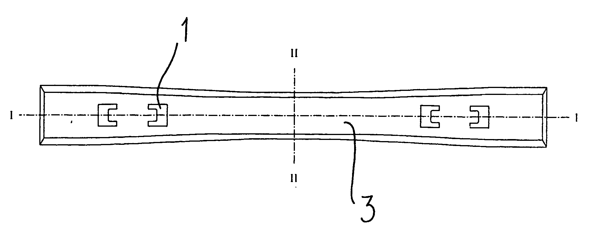
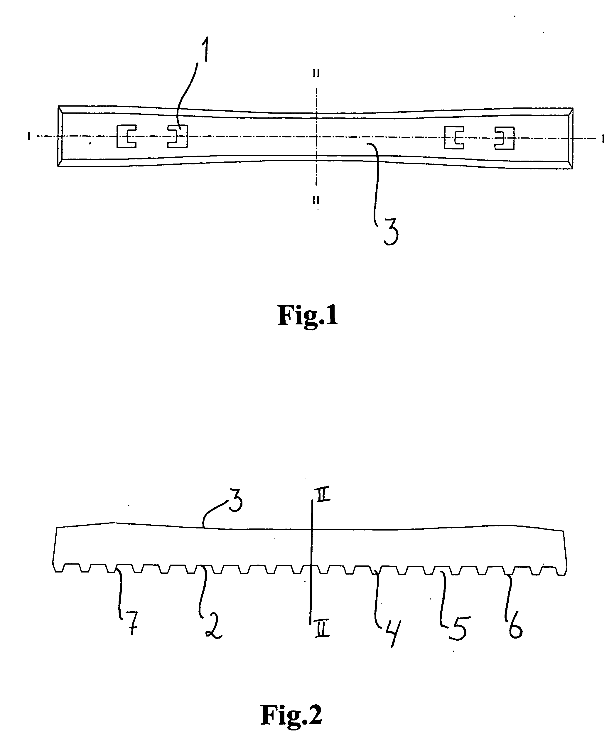
[0028] FIG. 1 is a view from above of a tie according to the present invention,

[0029] FIG. 2 is a longitudinal section of a tie, along line I-I in FIG. 1,

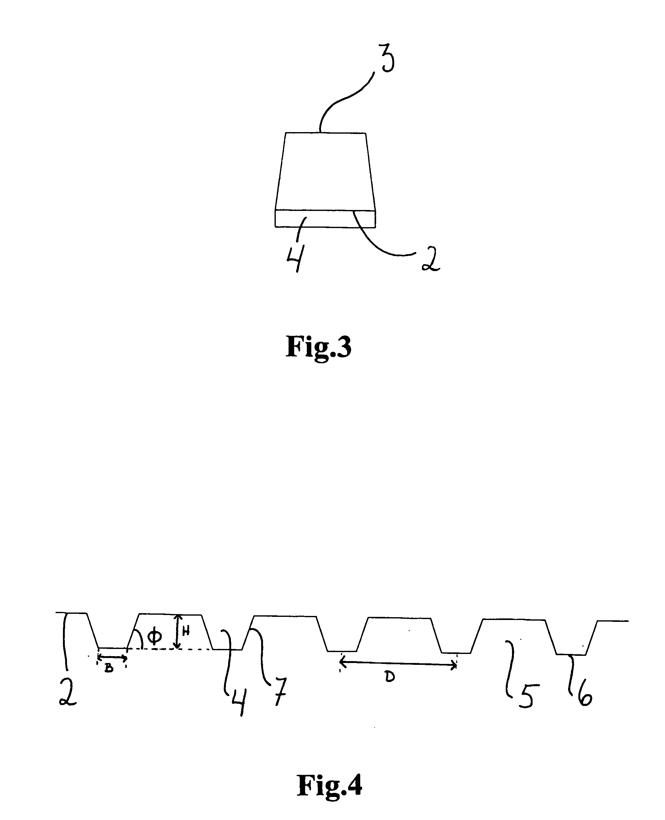
[0030] FIG. 3 is a cross section of a tie, along line II-II in FIG. 1 and 2, and

[0031] FIG. 4 is an enlarged section of the underside of a tie according to the present invention.

[0032] As shown in FIG. 1, a tie according to the present invention is mainly embodied as a traditional pot sleeper tie, with the exception of the underside. The upper side is provided with means 1 for fastening rails to the tie. The central part of the tie is a bit narrower than the end parts. The cross section of the tie (FIG. 3) has the form of a trapeze, wherein the face 2 turning down towards the foundation, is larger than the face 3 turning up towards the rails. With the exception of the underside, the tie may have any shape, as this is not part of the i...


PUM


Abstract

Present invention concerns a tie being the carrying element for rails in a railway track. The tie comprises means (1) for fastening the rails to the tie which in use is lying in a ballast bed of crushed stone at the formation plane of the line. At the underside (2) the tie is provided with a number of elevations (4), whose height (H) is 40-100% of Dmax of the crushed stone. Each elevation (4) protrudes across the tie, and constitutes a cogging towards the crushed stone, in the longitudinal direction of the tie.

Description

[0001] The invention relates to a tie as the carrying element for rails in a railway track, according to the preamble of patent claim 1.[0002] A conventional railway track is composed of two longitudinal steel rails attached by rail attachments to crosswise ties of wood, concrete or steel. The ties are supported by a ballast of crushed stone resting on the formation level of the line. It is an advantage to use all-welded railway tracks with continuous tracks, when considering speed, safety, comfort, maintenance needs and costs.[0003] When a train passes along the rails, the rails are loaded from the rolling stock. These loads are mainly vertical to the rails. However, due to train load, acceleration and braking, driving in curves and temperature variations, there are in addition, considerable horizontal forces affecting the rails both transverse and longitudinal to the rails.[0004] The longitudinal forces are extra large in curves due to the curvature. Upon a large increase in tempe...

Claims


Application Information

Patent Timeline
Patent Type & Authority Applications(United States)
IPC IPC(8): E01B3/28
CPCE01B3/28
Inventor LOHREN, ALF HELGENORDAL, RASMUS S.
Owner LEIV EIRIKSSON NYFOTEK
Why Eureka
Try Eureka