Intermediate composite part for forming reinforcement prosthesis

a composite part and reinforcement technology, applied in the field of reinforcement prosthesis, can solve the problems of postsurgical adhesion and erosion, difficult to completely produce a prosthesis in situ during the operation, and laborious and dangerous to achieve the effect of completely producing a prosthesis in situ

Inactive Publication Date: 2004-07-08
SOFRADIM PROD SAS
View PDF4 Cites 27 Cited by
  • Summary
  • Abstract
  • Description
  • Claims
  • Application Information

AI Technical Summary

Benefits of technology

[0040] In a preferred embodiment of the invention, the film which coats the textile support as described in the above paragraph is noncontinuous and preserves the macroporous texture of the textile support. The film then coats each thread and leaves free the volumes defining the macroporosity. Thus, the reinforcement preserves a pronounced macroporosity for rapid mechanical anchoring and immediate cell recolonization. Such coating with a noncontinuous film also makes it possible to temporarily stiffen the reinforcement and facilitate its handling by the surgeon. This latter property is particularly advantageous in laparoscopic surgery.
[0049] By virtue of the invention, the practitioner can freely form reinforcement prostheses by cutting out bands of suitable geometry from the intermediate composite part and placing them in such a way as to obtain a support which is nonaggressive, by virtue of the protected or occluded zone, with respect to the fragile tissue structures, and a rapid anchoring in the unprotected zones away from the fragile structures.

Problems solved by technology

For this reason, the porous nature of textile supports is often the cause of the development of postsurgical adhesions and erosions.
However, such a prosthesis is not especially desirable for protecting fragile structures, because of the hydrophobic and nonabsorbable nature of the silicone.
However, it would be tedious and indeed dangerous to completely produce a prosthesis in situ during the operation.
This would take up an enormous amount of time, would prolong the period of anesthesia necessary for the operation, and would increase the risks of complications.

Method used


Image

  • Intermediate composite part for forming reinforcement prosthesis
  • Intermediate composite part for forming reinforcement prosthesis

Examples


example 2

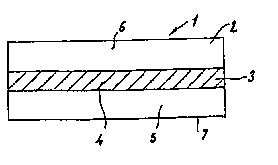
[0065] Starting from the same textile support and the same solution as were described in Example 1, the solution is sprayed onto the central band of the textile support which is to be protected. The spraying is carried out on one face of the textile. After 15 minutes to 2 hours of maturation of the gel formed on the surface of the textile, the solution is sprayed onto the other face. After the second spraying operation, the whole arrangement is left to dry under a flow of sterile air. The quantity of solution necessary to obtain a film with a final density of 0.133 g / cm.sup.2 is sprayed on. After maturation, the whole arrangement is sterilized with ethylene oxide.

[0066] An intermediate composite part is obtained whose central band of width 6 cm is an occluded zone according to the invention and whose lateral parts are devoid of absorbable material.

[0067] A strip with parallel edges and measuring 20.times.4 cm.sup.2 is cut out from this part in the width direction, giving a composite...


PUM

PropertyMeasurementUnit
thicknessaaaaaaaaaa
thicknessaaaaaaaaaa
temperatureaaaaaaaaaa

Abstract

The present invention relates to an intermediate composite part (1) designed for forming a composite reinforcement prosthesis and comprising: i) a porous textile support (2) which includes an arrangement of threads each composed of at least one filament of nonabsorbable polymer material, said textile support defining the free edge or edges (7) of the part, and ii) a hydrophilic absorbable material (3) covering said textile support, at least on one side of the latter, extending across the surface of what is called a protected zone (4) and creating, on each side of the latter, two unprotected zones (5, 6) of the textile support which are limited by said free edges and are devoid of any of said absorbable material. It also relates to a process for preparing such a part.

Description

[0001] This nonprovisional application claims the benefit of U.S. Provisional Application No. 60 / 423,378, filed Nov. 4, 2002.[0002] The present invention relates to an intermediate composite part for forming reinforcement prostheses for tissue structures.DESCRIPTION OF THE PRIOR ART[0003] Reinforcement prostheses generally serve to support the tissues and can be used in different areas of the body. These reinforcement prostheses may be designed for temporary implantation. In these cases, they are made of an absorbable material. They may, however, be designed for permanent implantation and they then consist, for example, of a textile support made of a nonabsorbable material.[0004] Textile supports are intrinsically adhesiogenic and fibrotic, irrespective of the nature of the tissues with which they are placed in contact. This property, when considered with respect to support tissues (muscles, aponeuroses, fascias, etc.), in fact constitutes an indispensable prerequisite for the quali...

Claims


Application Information

Patent Timeline
Patent Type & Authority Applications(United States)
IPC IPC(8): A61F2/04
CPCA61F2/04D06M15/15D06M15/03A61L27/48Y10T428/24994Y10T442/172Y10T442/40
Inventor THERIN, MICHELGRAVAGNA, PHILIPPE
Owner SOFRADIM PROD SAS
Why Eureka
Try Eureka