Composite amplifier with optimized linearity and efficiency

a technology of linearity and efficiency, applied in the direction of rf amplifier, amplifier modification to reduce non-linear distortion, transmission, etc., can solve the problems of non-linear output current of the auxiliary sub-amplifier, not only generating a desired voltage, and end up affecting the output of the composite amplifier, so as to achieve simple and effective implementation

Inactive Publication Date: 2004-07-15
TELEFON AB LM ERICSSON (PUBL)
View PDF7 Cites 79 Cited by
  • Summary
  • Abstract
  • Description
  • Claims
  • Application Information

AI Technical Summary

Benefits of technology

0023] Simple and effective implementation.
0024] Other advantages offered by the present invention will be appreciated upon reading of the below description of the embodiments of the invention.
0025] The invention, together with further objects and advantages thereof will be best understood by reference to the following description taken together with the accompanying drawings, in which:
0026] FIG. 1 is a schematic block diagram of a conventional Doherty amplifier;
0027] FIG. 2 is a schematic high-level block diagram of a radio transmitter based on a composite power amplifier,
0028] FIG. 3 is a schematic high-frequency model of a field-effect transistor (FET), including parasitic elements;

Problems solved by technology

It has also been shown that the non-linear output current of the auxiliary sub-amplifier in a Doherty-type composite amplifier not only generates a desired voltage at the main sub-amplifier, but also ends up as distortion in the output of the composite amplifier, mainly due to the reflection of the non-linear output current of the auxiliary amplifier at the impedance inverter.
In many cases, this distortion is much more severe than the distortion caused by non-linear parasitics.

Method used


Image

  • Composite amplifier with optimized linearity and efficiency
  • Composite amplifier with optimized linearity and efficiency
  • Composite amplifier with optimized linearity and efficiency

Examples


Embodiment Construction

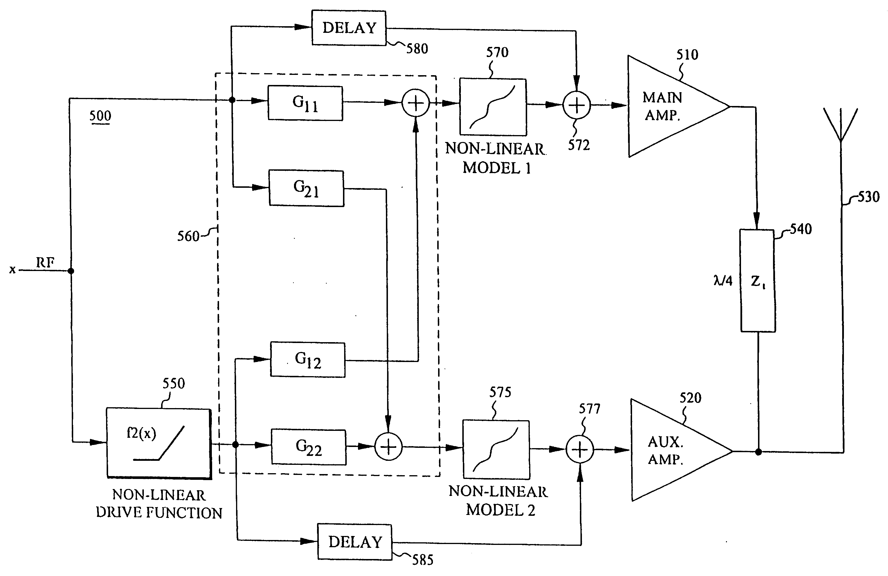
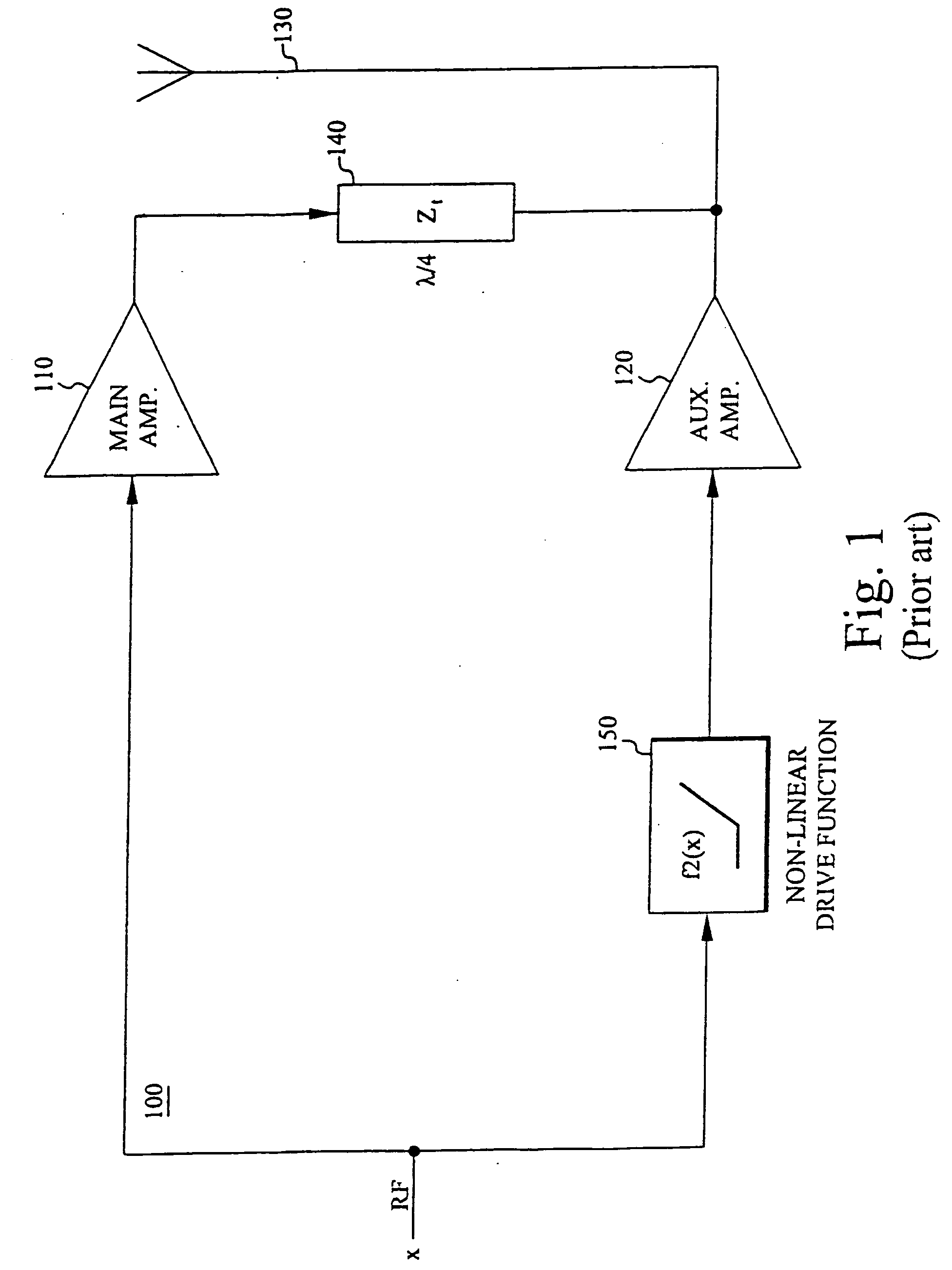
[0033] Composite amplifiers can be found in various applications in many fields of technology such as consumer electronics, radar technology and radio communication. In the following, the invention will be described with reference to a particular application within the field of radio communication. It should though be understood that the invention is not limited thereto, and that other applications are feasible as well.

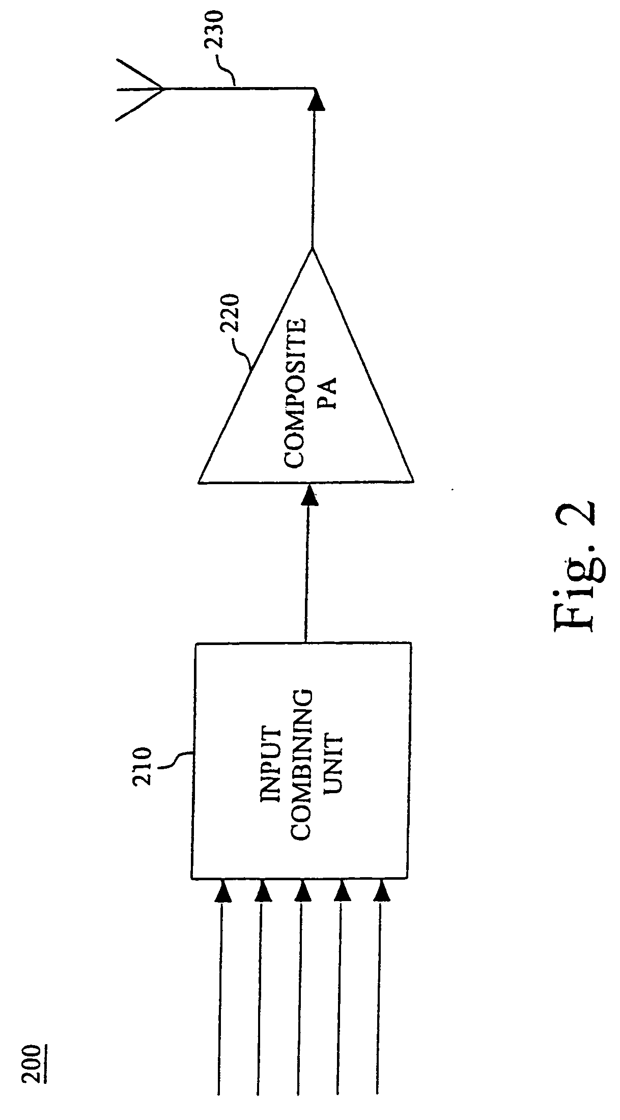
[0034] In a typical radio application, as schematically illustrated in the high-level block diagram of FIG. 2, a composite power amplifier is arranged in a radio transmitter for simultaneous amplification of several narrow-band channels. In a very basic realization, the transmitter 200 comprises a general input unit 210 for combining the input signals into a complex multi-channel signal, a composite power amplifier (PA) 220 for simultaneous amplification of the multiple channels and a transmission element 230. Such a basic realization of course requires that the input...


PUM


Abstract

The invention relates to a composite amplifier (500) based on a main amplifier (510) and an auxiliary amplifier (520), and compensation for non-linear amplifier behavior by means of respective non-linear models (570, 575) of parasitic. In order to provide proper excitation of the non-linear models. a filter network (560) based on a linear model of the output network of the composite amplifier is provided. The linear filter network (550) basically determines ideal output node voltages, which are used as input to the respective non-linear models for generating appropriate compensation signals. The compensation signals are finally merged into the input signals of the respective sub-amplifiers (510, 520), thus effectively compensating for the effects of the non-linear parasitics.

Description

[0001] The present invention generally relates to composite amplifiers and more particularly to techniques for optimizing the linearity as well as efficiency of such amplifiers.[0002] In cellular base stations, satellite communication systems as well as other communication and broadcasting systems of today, it is often desirable to amplify multiple radio frequency (RF) channels simultaneously in the same power amplifier instead of using a dedicated power amplifier for each channel. However, when using one and the same power amplifier for the simultaneous amplification of multiple RF channels spread across a fairly wide bandwidth, a high degree of linearity is required so that the phases and amplitudes of all the signal components are preserved in the amplification process.[0003] If the linearity is inadequate, the simultaneously amplified channels cross-modulate, causing interference in these and other channels. The non-linearities manifest themselves as cross-modulation of differen...

Claims


Application Information

Patent Timeline
Patent Type & Authority Applications(United States)
IPC IPC(8): H03F1/02H03F1/07H03F1/32H03F3/24H04B1/04
CPCH03F1/0288H03F1/32H04B1/0483H03F2200/451H03F3/24
Inventor HELLBERG, RICHARD
Owner TELEFON AB LM ERICSSON (PUBL)
Why Eureka
Try Eureka