
Impact energy absorber

Inactive Publication Date: 2004-07-22
OHTSUKA
View PDF6 Cites 9 Cited by
  • Summary
  • Abstract
  • Description
  • Claims
  • Application Information

AI Technical Summary

Benefits of technology

[0016] The present invention has been made in view of the above situation, and accordingly an object thereof is to provide an impact energy absorber that is lower in cost and easier to manufacture than the rectangular impact energy absorber, can absorb high energy like the rectangular impact energy absorber, and can provide its performance even if a load is applied from a direction over a wide angle range.
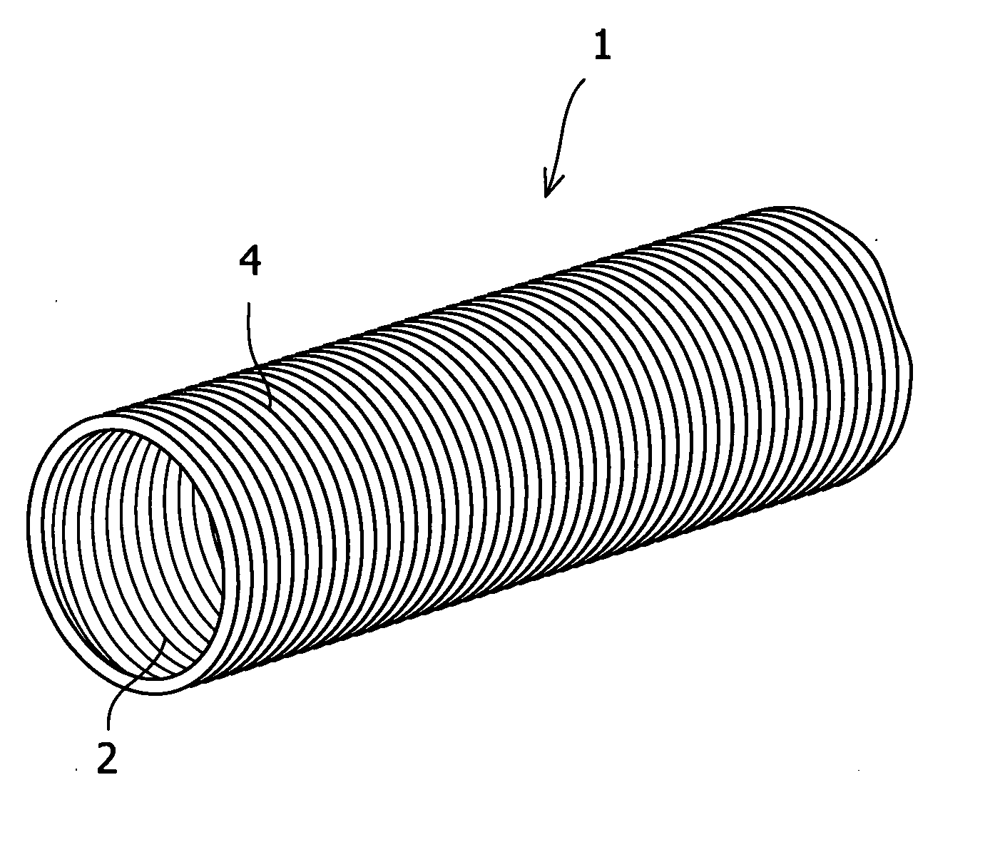
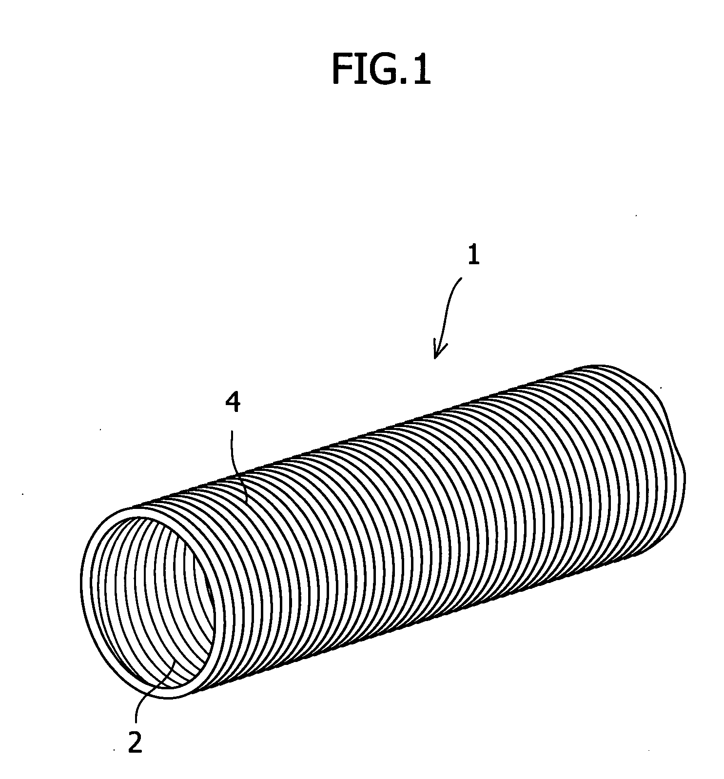
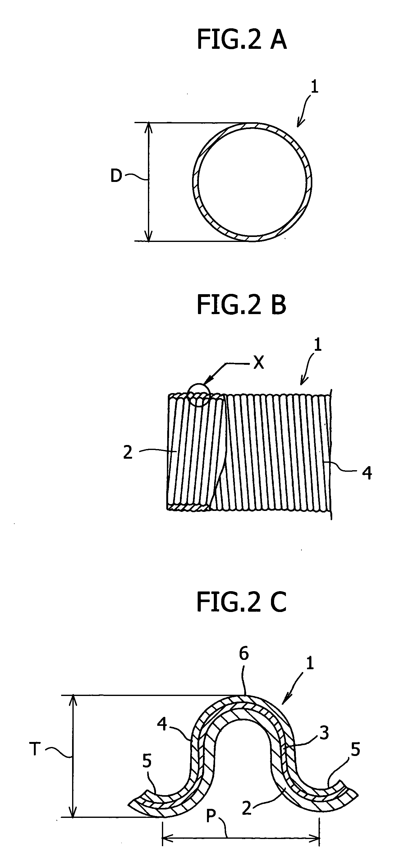
[0033] This energy absorber 1 is a flexible pipe having a circular cross section. The energy absorber 1 consists of three layers of an inner layer material 2, an intermediate layer material 3, and an outer layer material 4 in that order from the inside. As the inner layer material 2 and the outer layer material 4, a kraft paper is used, and as the intermediate layer material, a metal sheet, for example, iron foil or aluminum foil is used. In this embodiment, as the intermediate layer material, a hard aluminum foil is used. The inner layer material 2, the intermediate layer material 3, and the outer layer material 4 are formed by winding band-shaped materials in a spiral form. On these layer materials 2 to 4 which are lapped on each other, a concave portion 5 and a convex portion 6 are formed continuously in a corrugated form in the axial direction, and the concave portion 5 and the convex portion 6 are formed so as to be spiral. Therefore, the energy absorber 1 can be formed so as to extend in the axial direction according to the length of each material. Also, the energy absorber 1 can be cut to an appropriate length. Such an energy absorber can easily be bent at an angle larger than 90 degrees or into an S shape.

Problems solved by technology

Therefore, special equipment and technology are needed, and much time and labor are consumed, which leads to a high manufacturing cost for the energy absorber.
Also, the rectangular impact energy absorber has a directional property such that when a load is applied in the direction perpendicular to the opposed surfaces, high impact energy is absorbed, but when a load is applied in the diagonal direction, the performance is inferior.

Method used


Image

  • Impact energy absorber
  • Impact energy absorber
  • Impact energy absorber

Examples


Embodiment Construction

[0038] Next, the characteristics of the above-described impact energy absorber having a circular cross section will be described.

[0039] FIG. 3 shows a setup for a dynamic load characteristic test for the above-described impact energy absorber in conformity with FMVSS201 regulations. In this setup, a jig 11 of a square shape in cross section is fixed on a wall 10, and the energy absorber 1 is fixed to the jig 11 by fixing means such as a double-faced adhesive tape. Point O (forehead) at a position 25 mm higher than the center of gravity of a dummy 12, which is analogous to the shape of human head, is caused to collide with the energy absorber 1 at a speed of 24 km / h.

[0040] As a test subject for performance test, four types were used as shown in Table 2, examples 1 to 3 and a comparative example.

2TABLE 2 Size Corrugate Apparent Number Waveform (outside pitch tube of Al characteristics diameter) (mm) thickness (T) Al foil foils Kraft paper Comparative .O slashed.26 1.6 2.0 t0.10 .times...


PUM


Abstract

An object of the present invention is to provide an impact energy absorber which is easy to manufacture and low in cost and absorbs high impact energy. The impact energy absorber consists of an aggregate formed by lapping a kraft paper on the outside and inside of a metal sheet such as a hard aluminum foil, and is a flexible pipe having a circular cross-sectional shape and formed with concave and convex portions in a spiral form on the surface thereof. The outside diameter of the impact energy absorber is 20 to 50 mm, the pitch of the concave and convex portions is 1.4 to 2.0 mm, and the vertical width of the concave and convex portions is 2.3 to 3.2 mm. Energy is absorbed by plastic deformation in the radial direction of the energy absorber.

Description

BACKGROUND OF THE INVENTION AND RELATED ART STATEMENT[0001] 1. Field of the Invention[0002] The present invention relates to an impact energy absorber for absorbing an impact load applied to an automotive body or the like.[0003] 2. Description of Related Art[0004] A conventional impact energy absorber used for a motor vehicle is a pipe-shaped element having a circular cross section, and is disposed between an automotive body panel and a cabin interior panel. The impact energy absorber is constructed so that if an unexpected accident occurs when the motor vehicle is running and hence the passenger hits against the body panel, the aforementioned circular pipe is collapsed and plastically deformed, by which the impact energy is absorbed.[0005] However, the pipe-shaped impact energy absorber with a circular cross section cannot absorb high impact energy.[0006] Thereupon, an impact energy absorber capable of absorbing high impact energy, as shown in FIG. 9, has been developed (see Japane...

Claims


Application Information

Patent Timeline
IPC IPC(8): B62D25/02B60R21/02B60R21/04B62D25/04B62D25/06F16F7/12
CPCB60R21/04B60R21/0428F16F7/12B60R2021/0442B60R2021/0435
Inventor SHIMODA, AKIO
Owner OHTSUKA
Learn More