Dielectric filter, dielectric duplexer, and communication device
a technology of dielectric duplexer and dielectric filter, which is applied in the direction of resonators, electrical instruments, waveguides, etc., can solve the problems of small supply of new plating liquid and insufficient plating
- Summary
- Abstract
- Description
- Claims
- Application Information
AI Technical Summary
Benefits of technology
Problems solved by technology
Method used
Image

Examples
first embodiment
[0040] First Embodiment
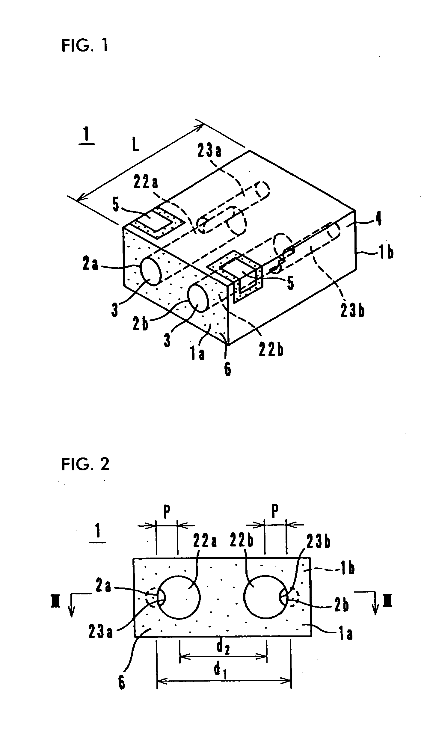
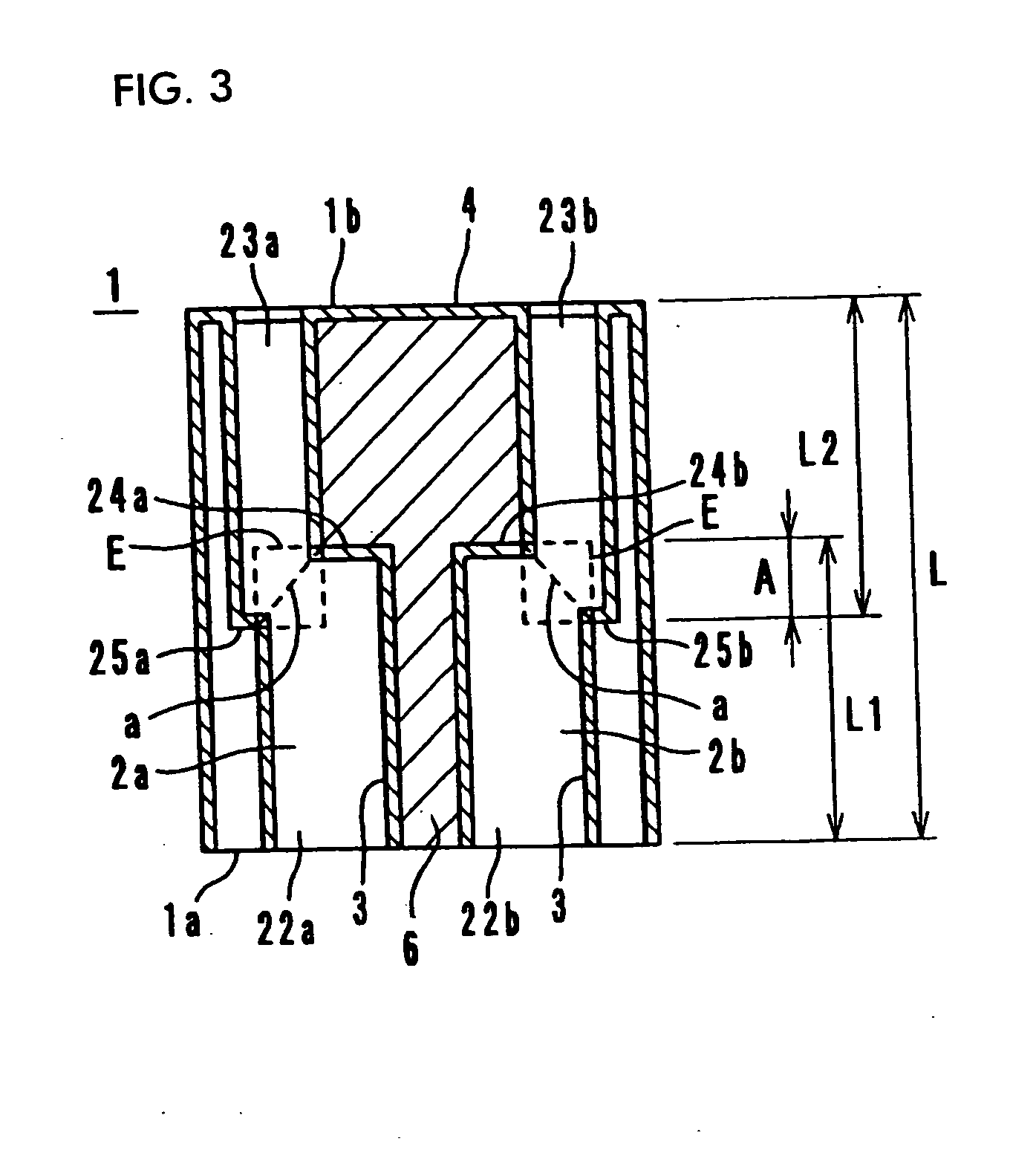
[0041] A first embodiment of the present-invention will now be described with reference to FIGS. 1 to 7. Referring first to FIG. 1, a dielectric filter 1 according to a first embodiment of the present invention has a pair of resonator holes 2a and 2b each extending between opposing surfaces 1a and 1b of the dielectric filter 1. The resonator holes 2a and 2b include large-diameter hole portions 22a and 22b, preferably having circular cross-sections, and small-diameter hole portions 23a and 23b, also preferably having circular cross-sections, and communicating with the large-diameter hole portions 22a and 22b, respectively. The distance d.sub.1 (FIG. 2) between the central axes of the small-diameter hole portions 23a and 23b is greater than the distance d.sub.2 between the central axes of the large diameter hole portions 22a and 22b with the result that the axes of the small-diameter hole portions 23a and 23b are displaced from those of the large-diameter hole p...
second embodiment
[0052] Second Embodiment
[0053] A second embodiment will now be described with reference to FIGS. 8 and 9. In a dielectric filter 1 of the second embodiment, as shown in FIG. 8, the interaxial distance d3 between small-diameter hole portions 23c and 23d is configured to be smaller than the interaxial distance d4 between large-diameter hole portions 22c and 22d. In addition, as shown in FIG. 9, the large-diameter hole portions 22c and 22d and the small-diameter hole portions 23c and 23d overlap each other in regions indicated by dotted lines E, in the axial directions of the resonator holes 2c and 2d, respectively. As a result, the connection portions a of the large-diameter hole portions 22c and 22d and the small-diameter hole portions 23c and 23d are larger in cross section than the connection portions b of the known dielectric filter (see FIG. 21). Thus, the resonator holes 2c and 2d have shapes which facilitate the passage of plating liquid therethrough, thereby allowing the forma...
third embodiment
[0055] Third Embodiment
[0056] A third embodiment of the present invention will now be described with reference to FIGS. 10 and 11. In a dielectric filter 1 of the third embodiment, as shown in FIG. 10, the interaxial distance d5 between small-diameter hole portions 23e and 23f is configured to be equal to the interaxial distance d6 between large-diameter hole portions 22e and 22f. In addition, as shown in FIG. 11, the large-diameter hole portions 22e and 22f and the small-diameter hole portions 23e and 23f overlap each other in regions indicated by dotted lines E, in the axial directions of the resonator holes 2e and 2f, respectively.
[0057] Since the dielectric filter 1 according to the third embodiment has a structure similar to those of the first and second embodiments, it offers advantages similar to the dielectric filters thereof. Moreover, this dielectric filter 1 offers more flexibility in designing the degree of electromagnetic field coupling.
PUM
 Abstract
Description
Claims
Application Information
 - R&D
- Intellectual Property
- Life Sciences
- Materials
- Tech Scout
- Unparalleled Data Quality
- Higher Quality Content
- 60% Fewer Hallucinations
Browse by: Latest US Patents, China's latest patents, Technical Efficacy Thesaurus, Application Domain, Technology Topic, Popular Technical Reports.
© 2025 PatSnap. All rights reserved.Legal|Privacy policy|Modern Slavery Act Transparency Statement|Sitemap|About US| Contact US: help@patsnap.com