
Steamer attachment

a technology of attachments and steamers, applied in the field of steamer attachments, can solve the problems of people currently having to change attachments between such tasks, affecting the effect of the effect of the attachment, and requiring different attachments,

Inactive Publication Date: 2004-07-29
TOP INNOVATIONS
View PDF16 Cites 73 Cited by
  • Summary
  • Abstract
  • Description
  • Claims
  • Application Information

AI Technical Summary

Benefits of technology

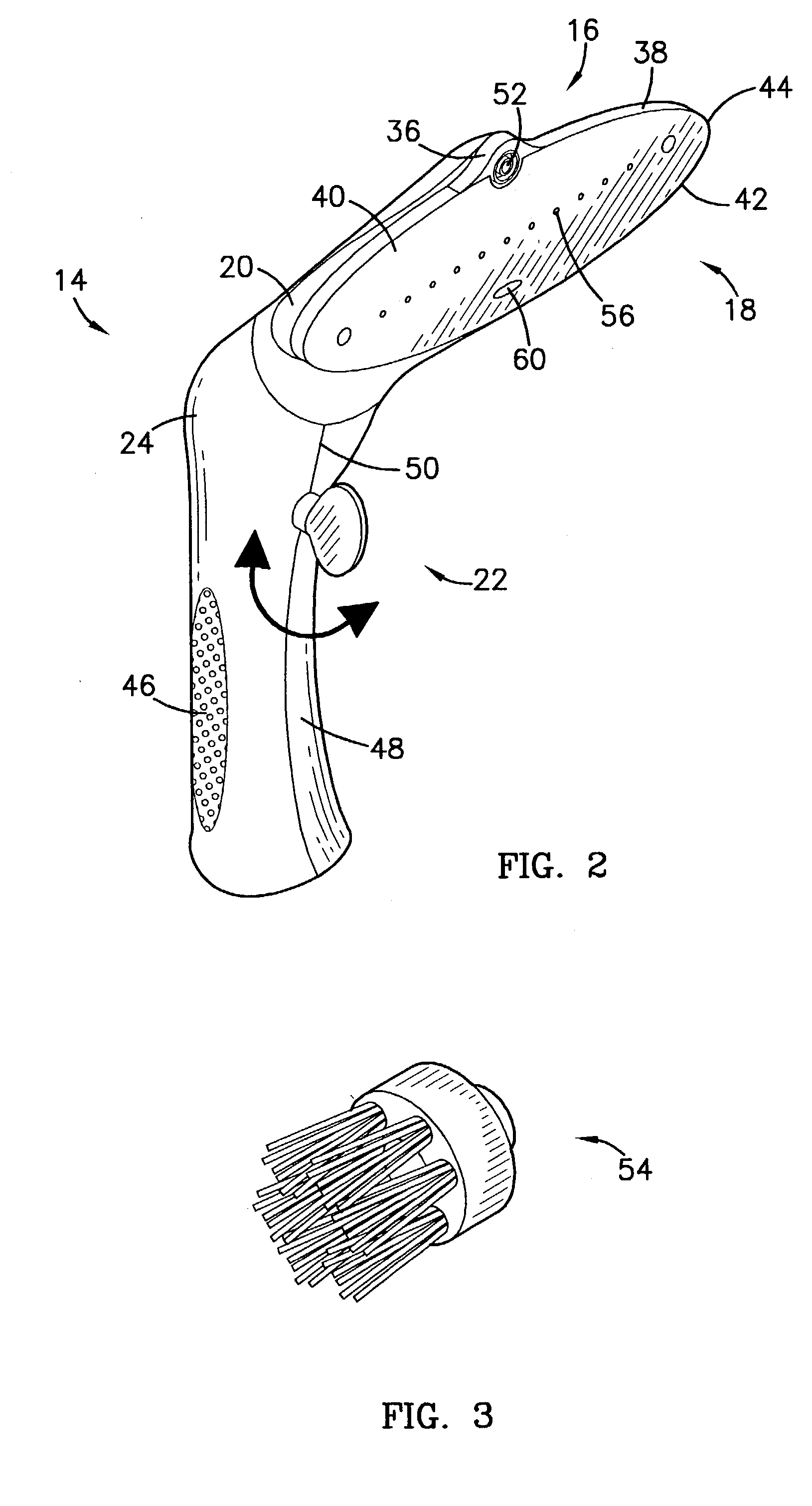
[0008] The attachment of the present invention broadly comprises a body having a head portion and a handle portion, a first and second steam distributor located in the head, and a valve located in the handle. The head is preferably aligned perpendicularly to the handle and includes a flange substantially centered along a top arcuate surface of a substantially flat face. The flange is preferably rounded and houses the first distributor. The face preferably includes the top arcuate surface which meets a bottom arcuate surface at opposing ends and houses the second distributor. Thus, the head preferably forms an oblong shape with no sharp corners, thereby making the head easy to manage and guide over the clothes being steamed.
[0009] The handle preferably includes knurled surfaces on either side and a contoured front surface, thereby providing a secure and comfortable grip. The valve is preferably located near a top end of the front surface, thereby allowing the user to operate the valve without releasing the handle. The handle may be either permanently joined to the hose of the steamer or secured to a fitting of the hose.
[0010] The first distributor preferably comprises a nozzle substantially centered within the flange and able to dispense steam generated by the steam generator of the steamer. The nozzle preferably concentrates the steam and may include a brush. The nozzle and the brush have been found to be highly effective for removing spots from the clothes.
[0012] The valve preferably directs the steam from the steam generator toward the first distributor, the second distributor, or both. More specifically, the valve preferably opens a first path toward the first distributor before closing a second path toward the second distributor. Additionally, with the valve in a mid-position, the steam may be directed to both distributors through both paths simultaneously. Thus, the steam always has at least one available path, in order to prevent pressure buildup within the steamer.
[0014] Alternatively, the user may select the second distributor to disperse the steam over the clothes, for general steaming. The user may secure the diffusor over the holes to further disperse the steam. In either case, the user may switch between distributors without turning the steamer off or risking pressure buildup.

Problems solved by technology

However, tasks, such as removing spots and wrinkles, are generally at odds and require different attachments.
Therefore, people currently have to change attachments between such tasks.
Thus, switching attachments can be very time consuming.
The wheels and casters become especially important when the steamer has been filled with water and is especially heavy.

Method used


Image

  • Steamer attachment
  • Steamer attachment
  • Steamer attachment

Examples


Embodiment Construction

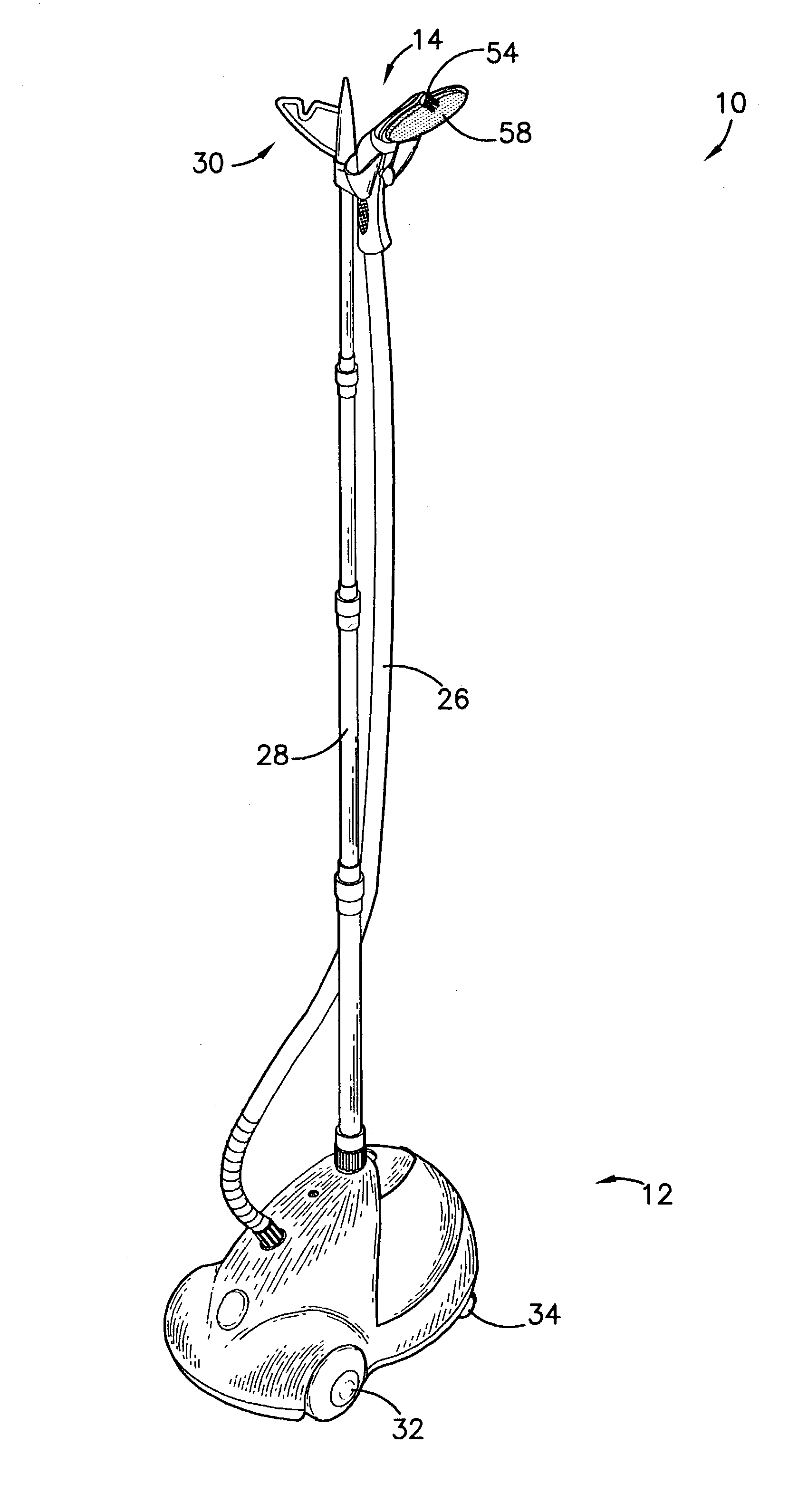
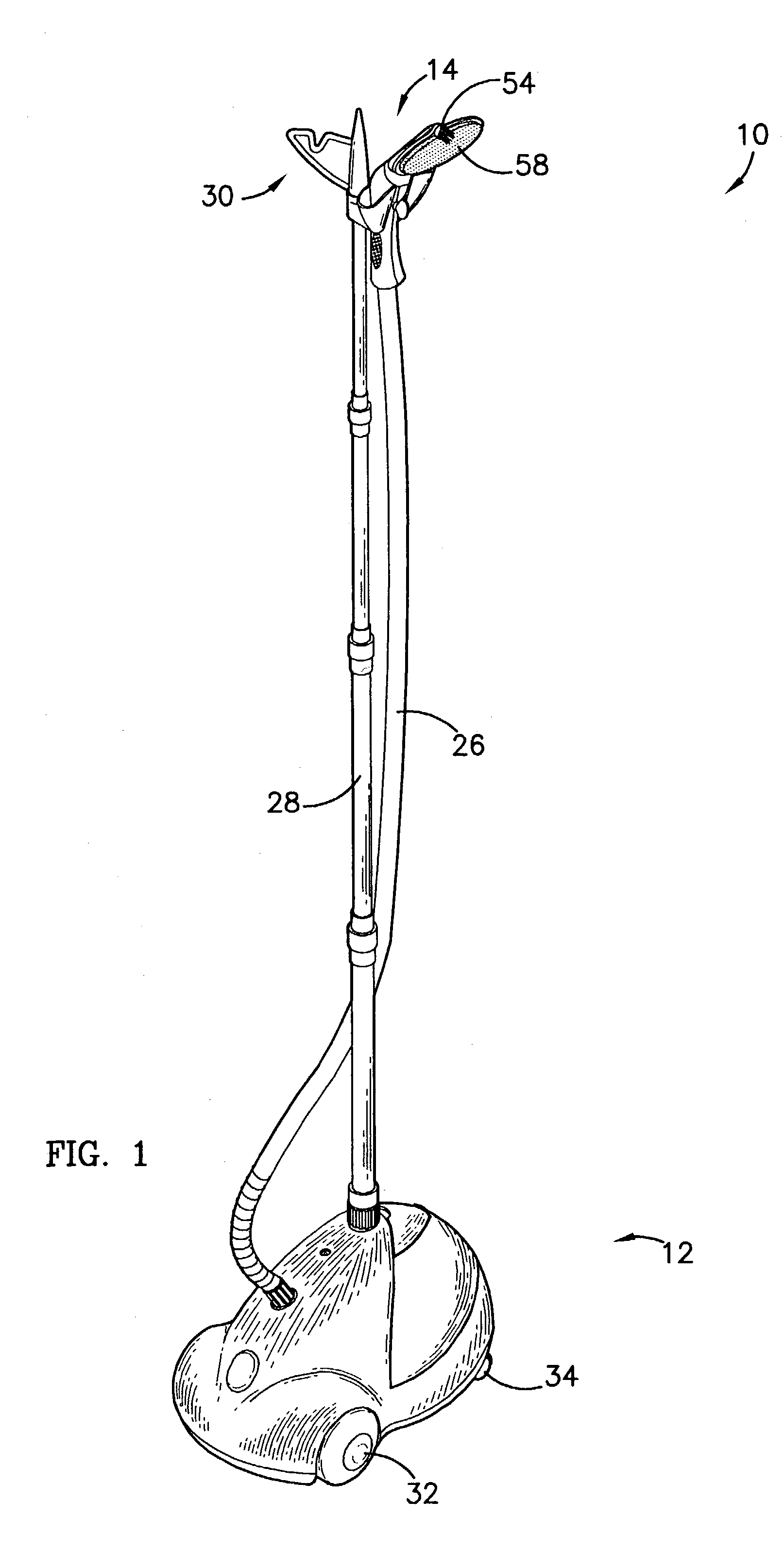
[0019] Referring to FIG. 1, the preferred steamer attachment 10 constructed in accordance with a preferred embodiment of the present invention is illustrated attached to a steamer 12. Referring also to FIG. 2 the attachment 10 broadly comprises a body 14, a first and second steam distributor 16,18 located in a head 20 of the body 14, and a valve 22 located in a handle 24 of the body 14.

[0020] The steamer 12 is preferably conventional and preferably includes a hose 26 and an internal steam generator. For example, the steamer 12 may be similar to that disclosed in "GARMENT STEAMING DEVICE WITH SAFETY NOZZLE", U.S. Pat. No. 5,609,047, hereby incorporated into the present application by reference. The steamer 12 also preferably includes a telescoping clothes support 28 with a clothes hanging bracket 30. Thus, clothes may be hung from the bracket 30 while a user steams them using the attachment 10. Additionally, the clothes may remain hanging from the bracket 30 until the user wishes to ...


PUM

PropertyMeasurementUnit
diameteraaaaaaaaaa
pressureaaaaaaaaaa
surface areaaaaaaaaaaa

Abstract

A steamer attachment (10) allows a user to selectively dispense steam from a steamer (12). The attachment (10) broadly comprises a body (14), a first and second steam distributor (16,18) located in a head (20) of the body (14), and a valve (22) located in a handle (24) of the body (14). The first distributor (16) preferably comprises a nozzle (52) to concentrate the steam and a brush (54). The second distributor (18) preferably comprises a plurality of holes (56) to disperse the steam. The second distributor (18) may also include a detachable diffusor (58) to further disperse the steam. The valve (22) preferably opens a first path toward the first distributor (16) before closing a second path toward the second distributor (18). Thus, the steam always has at least one available path, in order to prevent pressure buildup within the steamer (12).

Description

[0001] 1. Field of the Invention[0002] The present invention relates to steamer attachments. More particularly, the present invention provides a steamer attachment that allows a user to selectively dispense steam from different apertures of a steamer.[0003] 2. Description of Prior Art[0004] Steamers are frequently used in homes and businesses to clean and / or remove wrinkles from clothes, drapes and other items. However, tasks, such as removing spots and wrinkles, are generally at odds and require different attachments. Specifically, removing spots typically requires that steam is concentrated directly on the spot. Conversely, efficiently removing wrinkles typically requires that steam is dispersed over a wider surface area of clothes.[0005] Therefore, people currently have to change attachments between such tasks. In order to change attachments, the steamer must be shut-off to avoid steam burns and other hazards. Once the steamer has cooled down, the person may switch attachments an...

Claims


Application Information

Patent Timeline
Patent Type & Authority Applications(United States)
IPC IPC(8): D06F73/00
CPCD06F73/00
Inventor LEE, BENNY
Owner TOP INNOVATIONS
Learn More