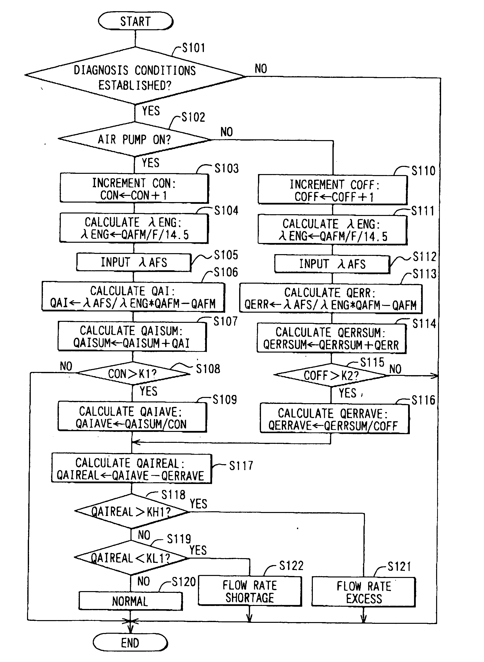
Secondary air supply abnormality detection system
an abnormality detection and air supply technology, applied in the direction of machines/engines, electrical control, exhaust treatment electric control, etc., can solve the problems of increasing the cost, large calculation error generation, and increasing the temperature of the catalys
- Summary
- Abstract
- Description
- Claims
- Application Information
AI Technical Summary
Benefits of technology
Problems solved by technology
Method used
Image
Examples
first embodiment
[0026] (First Embodiment)
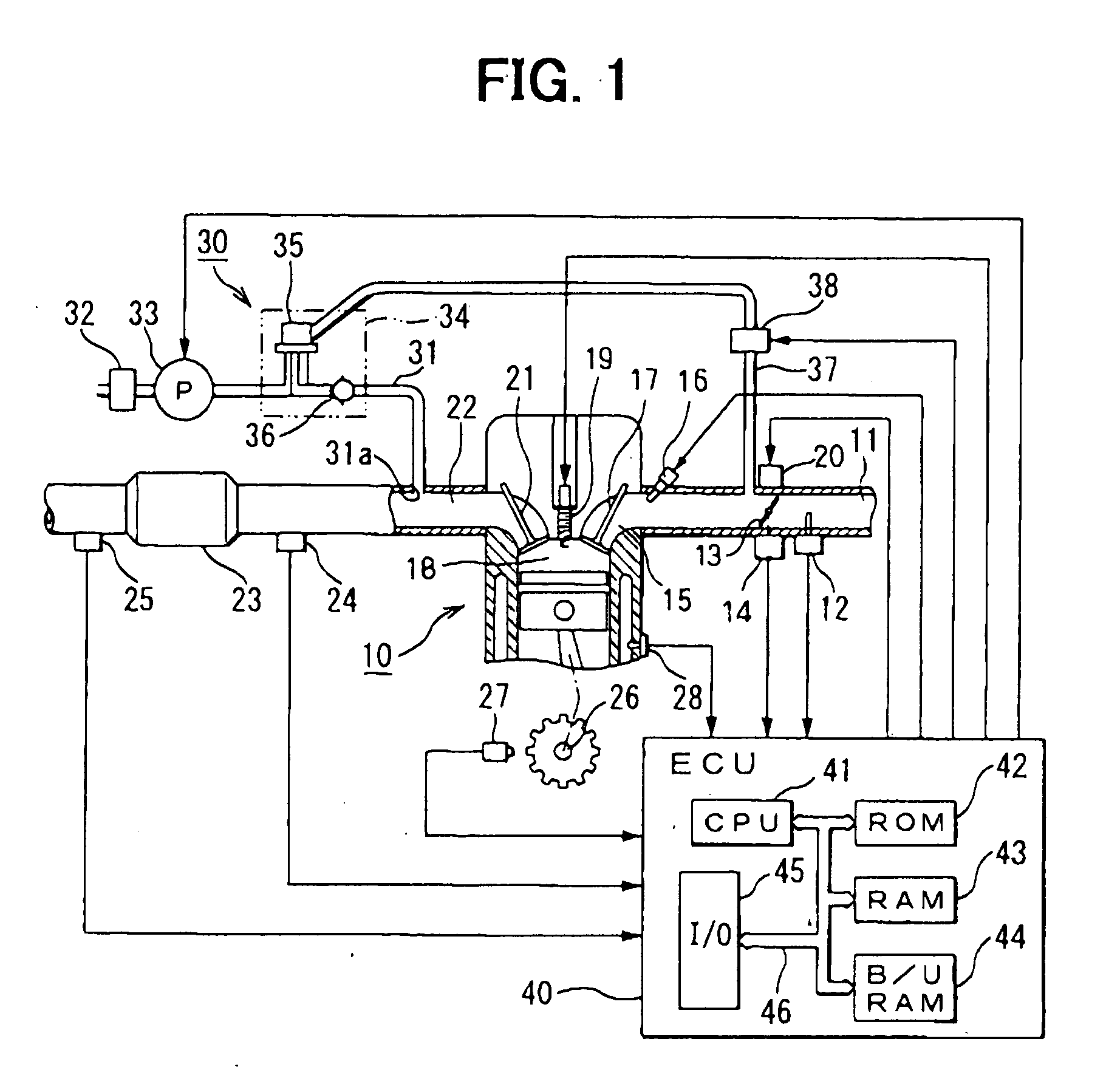
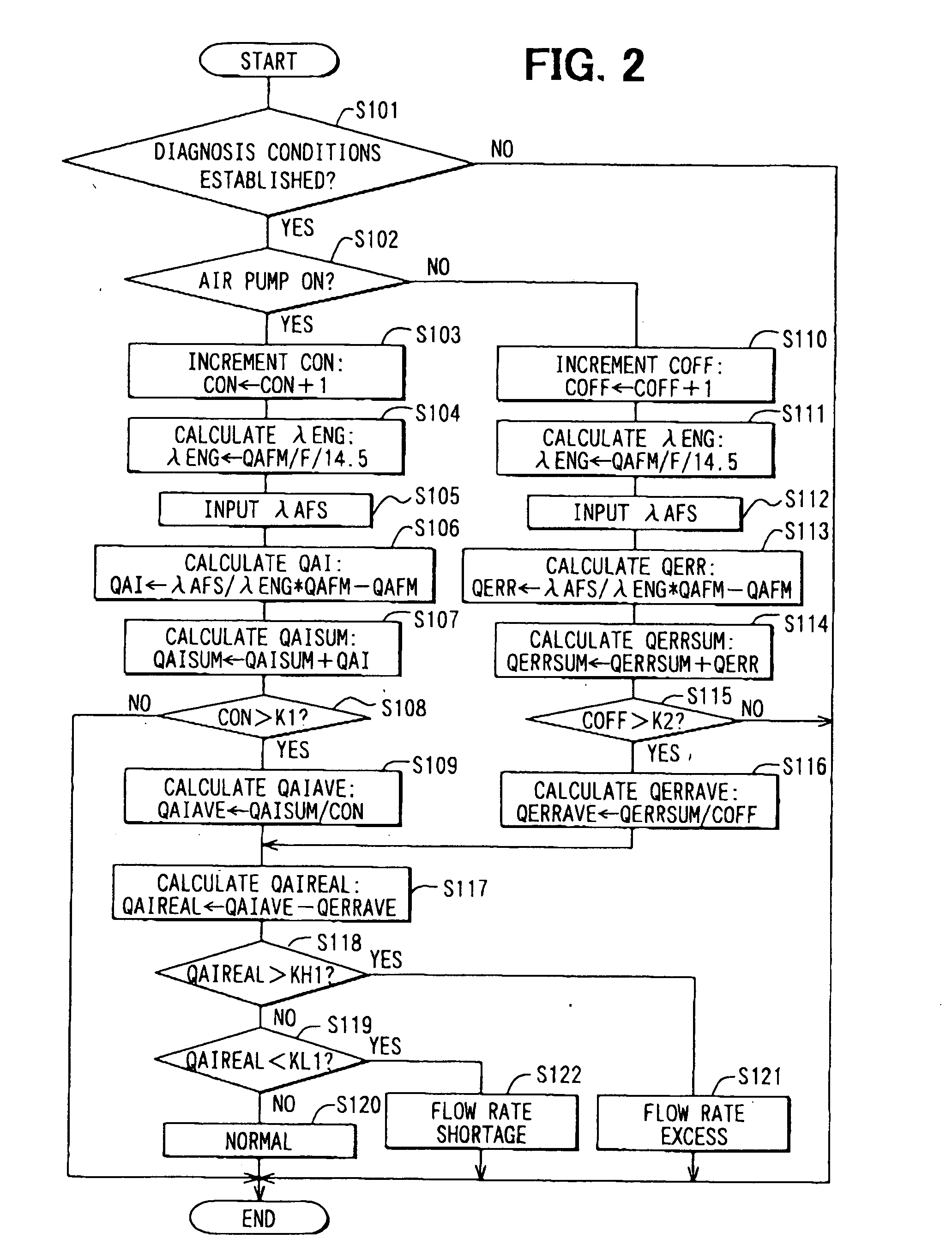
[0027] Referring to FIG. 1, an internal combustion engine 10 having a secondary air supply abnormality detection system according to the first embodiment of the present invention is illustrated. As shown in FIG. 1, an airflow meter 12 for sensing a quantity of intake air supplied through an air cleaner is disposed on an upstream side of an air intake passage 11 of the engine 10. A throttle valve 13 for regulating the air intake quantity to the engine 10 is disposed downstream of the airflow meter 12. A direct current motor 20 as an actuator constituting an electronic throttle structure drives the throttle valve 13 to open or close. A throttle opening degree sensor 14 for sensing an opening degree of the throttle valve 13 is disposed on the throttle valve 13. In the air intake passage 11, an injector (a fuel injection valve) 16 is disposed near an intake port 15 of each cylinder of the engine 10.
[0028] Mixture of intake air of a quantity defined by the thrott...
second embodiment
[0051] (Second Embodiment)
[0052] Next, processing steps of secondary air supply abnormality detection performed by the CPU 41 of the ECU 40 used in the secondary air supply abnormality detection system of the internal combustion engine 10 according to the second embodiment of the present invention will be explained based on a flowchart shown in FIG. 4 and the time chart shown in FIG. 3. The secondary air supply abnormality detection routine shown by the flowchart in FIG. 4 is performed by the CPU 41 repeatedly at a predetermined time interval. The secondary air supply abnormality detection system of the second embodiment has the same structure as the first embodiment.
[0053] First, in Step S201 of the flowchart in FIG. 4, like the first embodiment, it is determined whether conditions for the diagnosis are established or not. The conditions for the diagnosis include a condition that the air-fuel ratio sensor 24 is active, a condition that the operating state is steady (without rapid c...
third embodiment
[0064] (Third Embodiment)
[0065] Next, processing steps of secondary air supply abnormality determination performed by the CPU 41 of the ECU 40 used in the secondary air supply abnormality detection system for the internal combustion engine 10 according to the third embodiment will be explained based on a flowchart shown in FIG. 5. The CPU 41 performs the secondary air supply abnormality determination routine at a predetermined time interval.
[0066] First, in Step S301 shown in FIG. 5, it is determined whether duration t.sub.air after the air pump 33 is switched from an operating state (ON) to a dormant state (OFF) is longer than a predetermined period t.beta.. The predetermined period t.beta. is a period for stabilizing the secondary air downstream air-fuel ratio .lambda.AFS after the supply of the secondary air is stopped. If the result of the determination in Step S301 is "NO", the routine is ended without performing anything.
[0067] On the other hand, if the result of the determina...
PUM
 Abstract
Description
Claims
Application Information
 - R&D
- Intellectual Property
- Life Sciences
- Materials
- Tech Scout
- Unparalleled Data Quality
- Higher Quality Content
- 60% Fewer Hallucinations
Browse by: Latest US Patents, China's latest patents, Technical Efficacy Thesaurus, Application Domain, Technology Topic, Popular Technical Reports.
© 2025 PatSnap. All rights reserved.Legal|Privacy policy|Modern Slavery Act Transparency Statement|Sitemap|About US| Contact US: help@patsnap.com


