Vacuum processing apparatus

a vacuum processing and vacuum technology, applied in the direction of chemical vapor deposition coating, coating, electric discharge tube, etc., can solve the problems of large overall processing apparatus size, uneven thickness distribution of film deposited on the substrate, plasma disorder, etc., to reduce the size of the overall processing apparatus, reduce the effect of plasma disorder

Inactive Publication Date: 2004-08-05
TOKYO ELECTRON LTD
View PDF22 Cites 45 Cited by
  • Summary
  • Abstract
  • Description
  • Claims
  • Application Information

AI Technical Summary

Benefits of technology

0012] It is an object of the present invention to provide a vacuum processing apparatus which can prevent plasma from spreading into a carrier port for carrying a substrate to be processed into and out of a chamber when plasma is generated, which can eliminate the disorder of plasma to ensure a uniform plasma processing, which is simple in structure and which can be made small in size.

Problems solved by technology

If this processing chamber 2 is applied to, for example, a CVD apparatus, problems occur.
One of these problems is that the distribution of the thickness of a film deposited on the substrate becomes uneven.
This disadvantageously makes the overall processing apparatus large in size.
Due to this, if plasma is generated, plasma spreads toward the lower side of the stage 4 through these clearances 8, disadvantageously making plasma density into disorder.
With this technique, however, it is necessary to provide motors and driving units independently of one another for the plural magnetic members so that the magnetic members generate magnetic fields in the direction perpendicular to the plasma flow, which disadvantageously complicates the structure of the apparatus.

Method used


Image

  • Vacuum processing apparatus
  • Vacuum processing apparatus
  • Vacuum processing apparatus

Examples


first embodiment

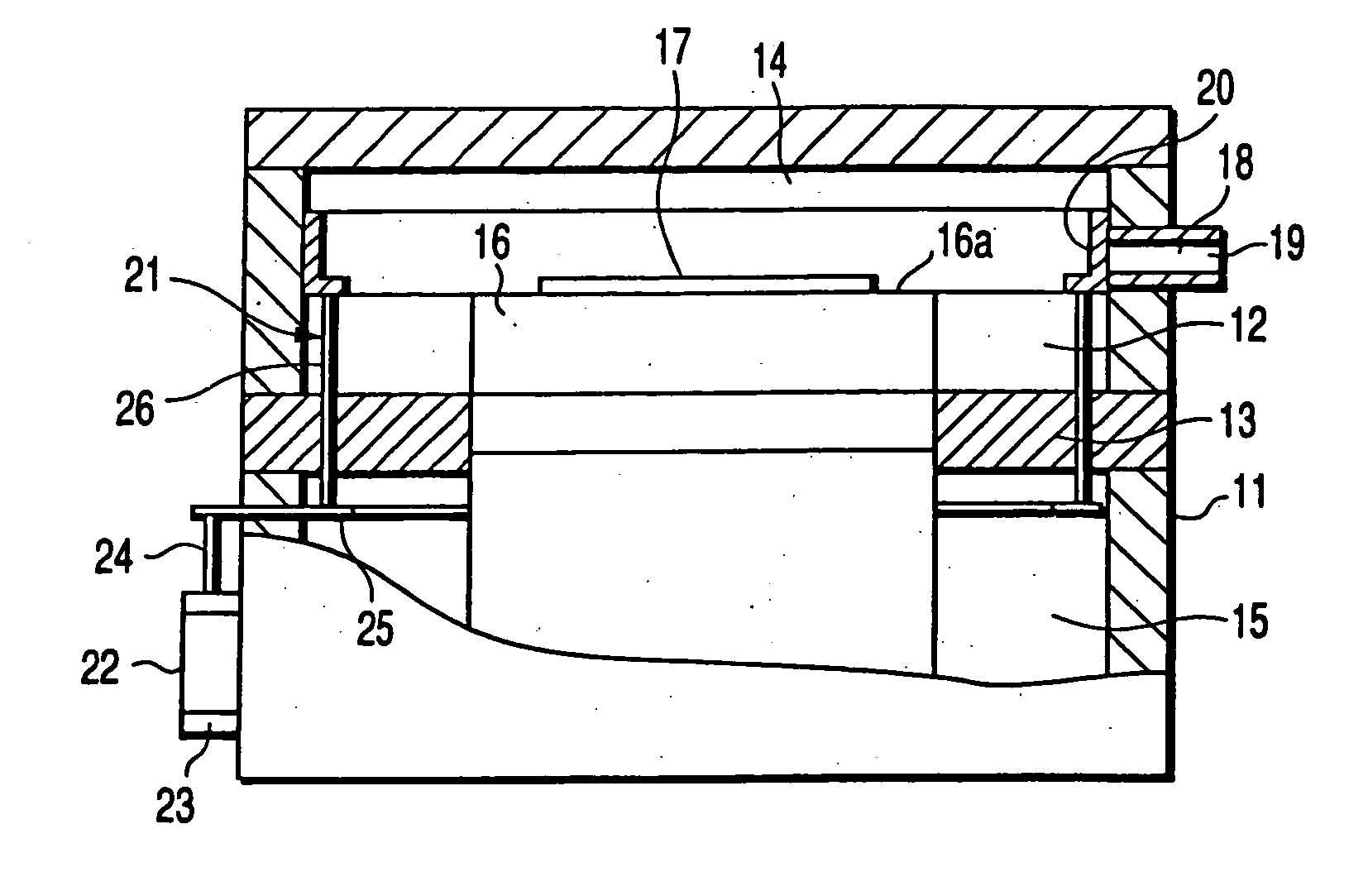
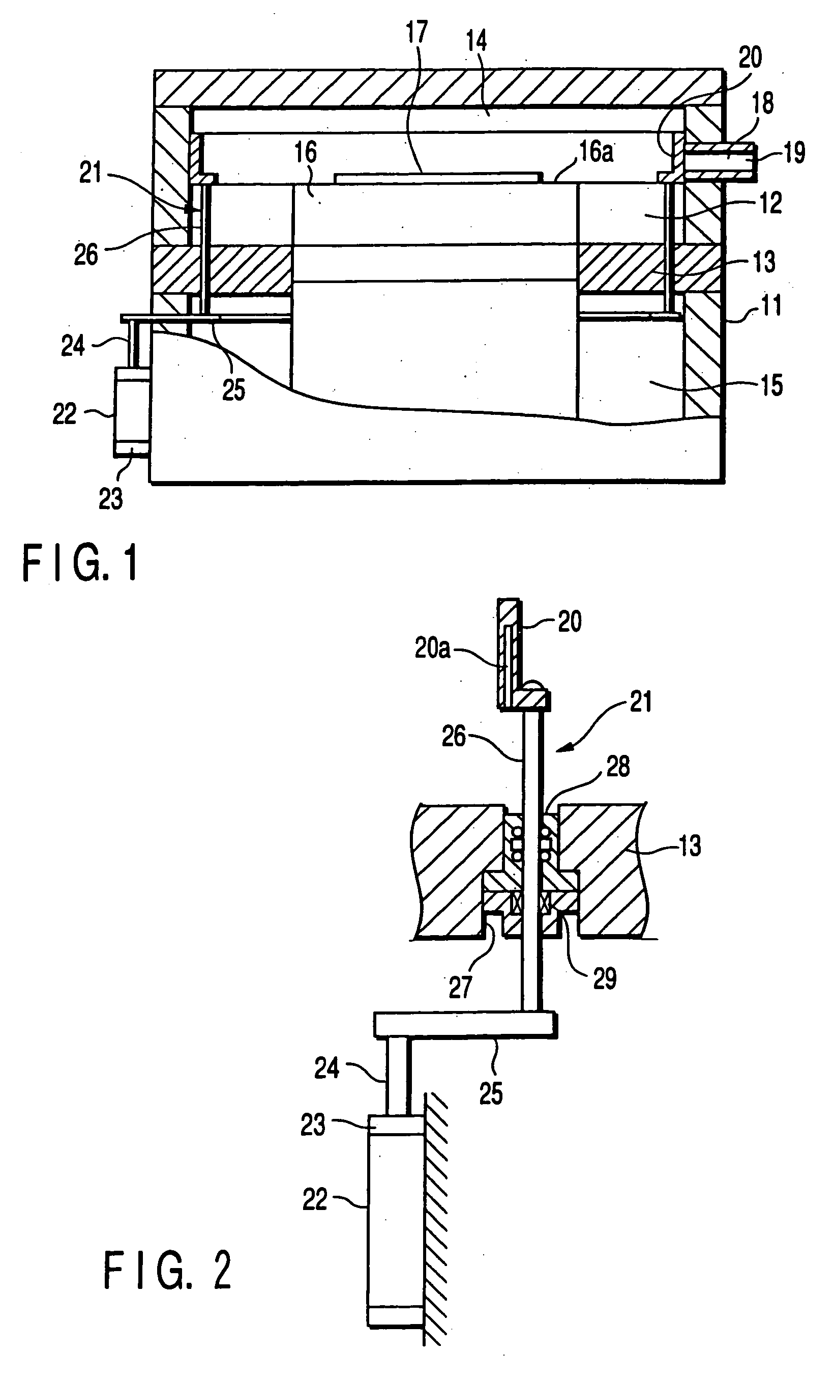
[0028] FIGS. 1 through 3 show a first embodiment for carrying out the invention. FIG. 1 is a longitudinal front view of a vacuum processing apparatus, FIG. 2 is a front view of a shutter drive unit and FIG. 3 is a perspective view of a shutter.

[0029] As shown in FIG. 1, a processing chamber 11 constituting the main body of a vacuum processing apparatus is formed out of a conductive material such as, for example, aluminum. The interior of the processing chamber 11 is vertically partitioned by a ring-shaped partition wall 13 into an upper portion used as a vacuum processing area 14 and a lower portion used as an atmospheric area 15.

[0030] A stage 16 is provided at the center of this partition wall 13. An insulating member made of quartz or the like is arranged on the upper surface of this stage 16 to provide a mounting surface 16a on which a substrate to be processed 17, such as a liquid crystal glass substrate or a semiconductor wafer, is mounted.

[0031] The surface of the stage 16 is...

second embodiment

[0044] Next, a vacuum processing apparatus for carrying out the present invention will be described.

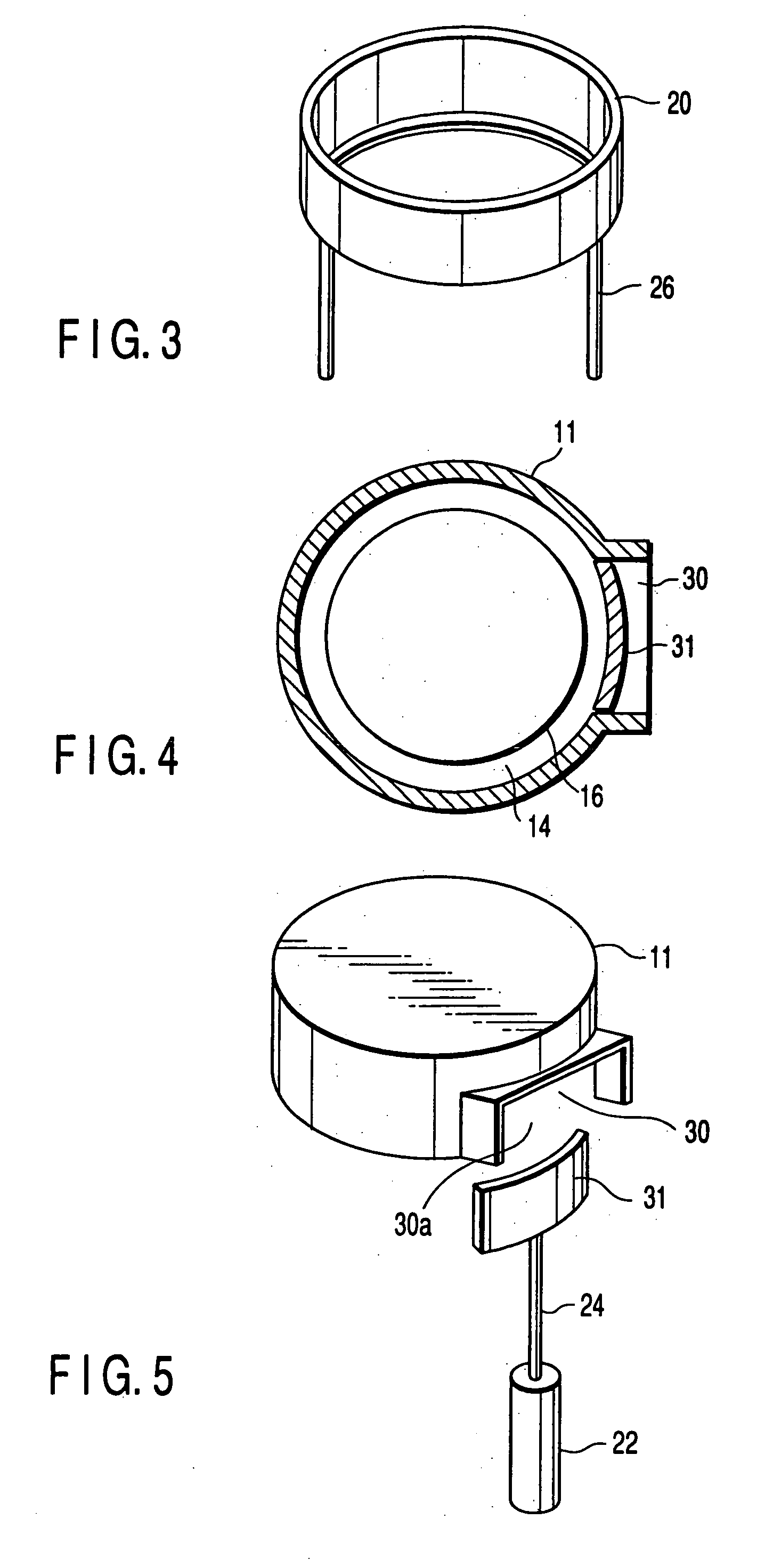
[0045] FIG. 4 is a cross-sectional plan view of a processing chamber 11 constituting a vacuum processing area 14 and FIG. 5 is a perspective view of a shutter drive unit. In this embodiment for carrying out the invention, the same constituent elements as those in the first embodiment for carrying out the invention described above are denoted by the same reference symbols and no detailed description will be given thereto.

[0046] A carrier port 30 is provided on a part of the peripheral wall of the processing chamber 11 of this vacuum processing apparatus and opened to have a flat rectangular shape along the peripheral direction of the processing chamber 11. The carrier port 30 has also an opening portion 30a on a lower end thereof.

[0047] Further, a gate 31 airtight opening and closing the carrier port 30 is provided in the vacuum processing area 14 to be freely elevated. This gate 31 i...

third embodiment

[0050] Next, a vacuum processing apparatus in a third embodiment for carrying out the present invention will be described.

[0051] FIG. 6 is a longitudinal sectional front view of a vacuum processing apparatus in this embodiment for carrying out the present invention.

[0052] A processing chamber 41 constituting the main body of this vacuum processing apparatus is formed out of a conductive material such as aluminum. The interior of the processing chamber 41 is vertically partitioned by a ring-shaped partition wall 42 into an upper portion used as a vacuum processing area 43 and a lower portion used as an atmospheric area 44.

[0053] A stage 45 is provided at the center of this partition wall 42. An insulating member made of quartz or the like is arranged on the upper surface of this stage 45 to provide a mounting surface 45a on which a substrate to be processed 46, such as a liquid crystal glass substrate or a semiconductor substrate, is mounted. Also, a disk-shaped evacuation plate 56 i...


PUM

PropertyMeasurementUnit
atmospheric pressureaaaaaaaaaa
densityaaaaaaaaaa
thicknessaaaaaaaaaa

Abstract

This invention is a vacuum processing apparatus comprising of a vacuum processing area (14) having a stage (16) on which a substrate to be processed (17) is mounted, and a carrier port (18) provided on a periapheral wall of a processing chamber (11) forming the vacuum processing area (14) and carrying the substrate (17) onto and off the stage (16), for generating plasma in the vacuum processing area (14) and subjecting the substrate (17) on the stage (16) to a plasma processing, wherein a shutter (20) closing the carrier port (18) to prevent the plasma from being disordered when the plasma is generated in the vacuum processing chamber is provided.

Description

[0001] The present invention relates to a vacuum processing apparatus for forming a film or etching for a substrate to be processed by a semiconductor manufacturing technique using plasma.[0002] There is normally known a plasma processing apparatus forming a thin film, such as a CVD (chemical vapor deposition) system, or for selective etching, such as an RIE (reactive ion etching) system, using plasma with respect to the surface of a substrate to be processed while disposing the substrate, e.g., a liquid crystal glass substrate or a semiconductor wafer, in a processing chamber which is exhausted by an exhausting system to form a vacuum.[0003] FIG. 10 is a schematic block diagram of a conventional plasma processing apparatus.[0004] This plasma processing apparatus 1 has a cylindrical processing chamber 2 exhausted by an exhausting system, which is not shown, and a stage 4 supported by a driving shaft 3 such as a ball screw and provided in the chamber 2. The stage 4 is made flat so th...

Claims


Application Information

Patent Timeline
Patent Type & Authority Applications(United States)
IPC IPC(8): H01J37/32H01L21/00
CPCH01J37/32458H01L21/67126H01L21/67069
Inventor HIROSE, JUNOZAWA, JUNOKUBO, TOMOYAFUJI, TATSUYA
Owner TOKYO ELECTRON LTD
Why Eureka
Try Eureka