Conveyance method and apparatus for processing step

a technology of conveying apparatus and processing step, which is applied in the direction of lighting and heating apparatus, charge manipulation, furniture, etc., can solve the problems of not being able to adjust the angle of the vehicle body, the coating attitude or angle cannot be controlled for each vehicle model and vehicle body shape, and the vehicle body shape is complicated

Inactive Publication Date: 2004-08-05
DAIFUKU CO LTD
View PDF1 Cites 19 Cited by
  • Summary
  • Abstract
  • Description
  • Claims
  • Application Information

AI Technical Summary

Problems solved by technology

Furthermore, due to improvements in travel safety and the like, vehicle body shapes have become more complicated over the years.
However, in the prior art references 1 and 2, it is not possible to adjust the angle of the vehicle body upon being introduced into the processing liquid or the angle of the vehicle body upon being removed from the same, for each different body shape.
Hence there has been a problem in that the coating attitude or angle cannot be controlled for each vehicle model and vehicle body shape.

Method used


Image

  • Conveyance method and apparatus for processing step
  • Conveyance method and apparatus for processing step
  • Conveyance method and apparatus for processing step

Examples


second embodiment

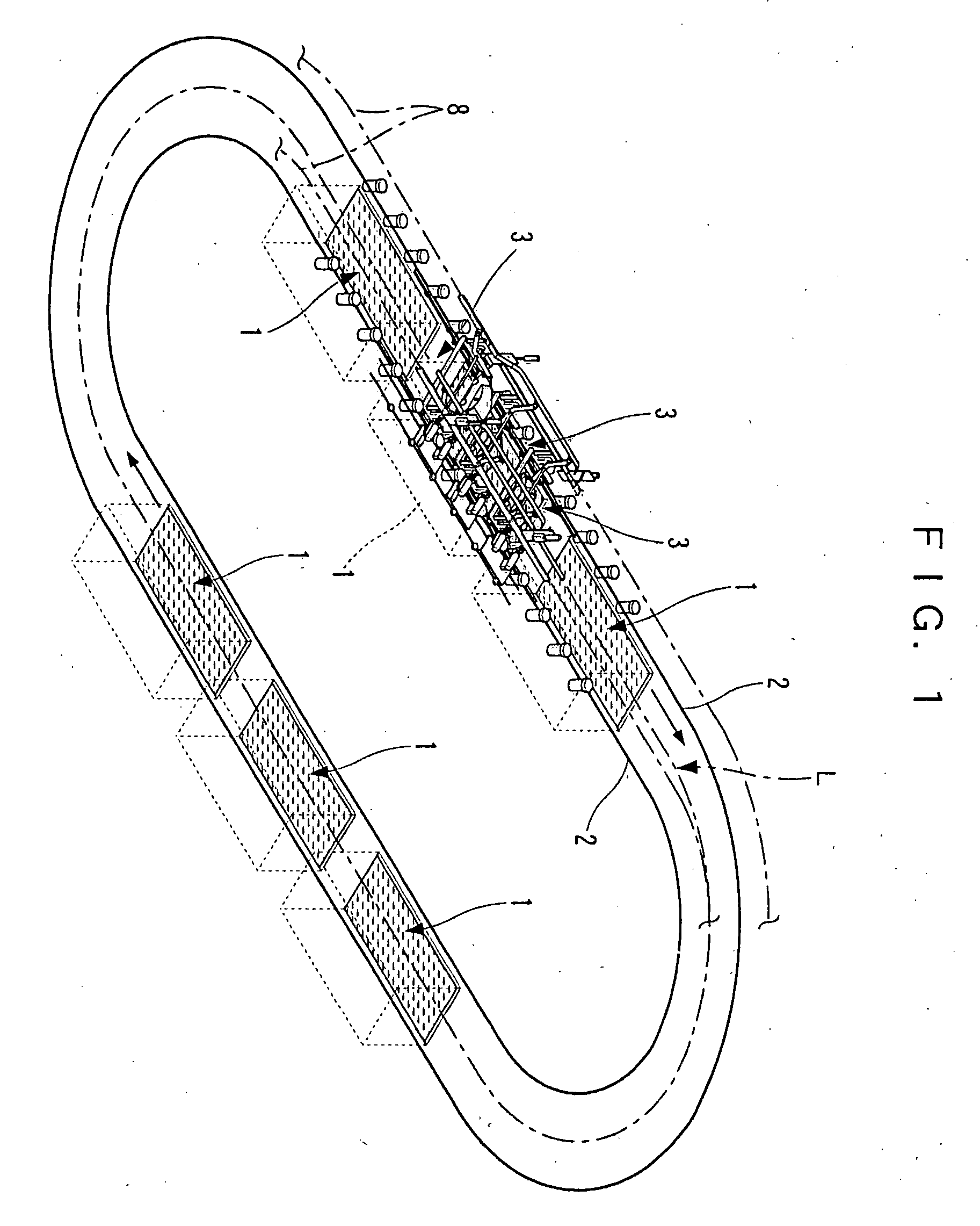
[0069] In the second embodiment described above, an intermittent travel system was adopted for the travel mode of the travelling carriages 43, 81, whereby the travelling carriages 43, 81 are caused to move back and forth reciprocally, and the travelling carriages 43 are caused to wait at standby in front of the dip tank 1 during the coating operation, but it is also possible to adopt a continuous travel system by providing an endless type travel path in which a plurality of travel carriages 43, 81 are caused to travel in a cyclical fashion.

third embodiment

[0070] As shown in FIG. 12, in a third embodiment of a coating line apparatus, it is possible to adopt a composition wherein tilting arms 21 are caused to incline downwards, thereby immersing a vehicle body M in a coating liquid, in addition to which, the angle of the vehicle body M is controlled and the rotating arms 21 are then rotated upwards thus removing the vehicle body M from the coating liquid, while the conveyance carriage 3 remains in a halted state.

[0071] In other words, here, the arm tilting device 16 is constituted in such a fashion that an operating cam rail 16C is provided raisably and lowerably in a portion of the restricting rail 19, in a position corresponding to the cam rollers 15 of the conveyance carriage 3 in a halt position, and the operating cam rail 16C is driven so as to be raised or lowered, by a raising and lowering drive device 16D. Furthermore, the angle adjusting drive section 31 omits the travelling carriages 43, and comprises an angle adjusting drive...

fourth embodiment

[0073] In the first to third embodiments, the vehicle body supporting frame 14 is raised and lowered by means of tilting arms 12 which are rotated upwards and downwards, but as illustrated in FIG. 13 and FIG. 14, in this fourth embodiment, the operating arms are constituted by parallel link arms 101 based on a pantograph system, in such a manner that the vehicle body supporting frame 14 is raised and lowered in a vertical direction. Members which are the same as those of the previous embodiments are similarly labelled, and description thereof is omitted here.

[0074] Namely, a support bearing 103 is provided on a suspension section 102a of a carriage frame 102 of a conveyance carriage 3 formed having a square frame shape in plan view, and a pair of left and right-hand parallel link arms 101 are supported extendably in the downward direction on the support bearing 103, by means of a support axle 104. These parallel link arms 101 each comprise a pair of front and rear base side arms 101...


PUM


Abstract

An operating arm (12) supported on a movable body (3) is operated to move downwards, and a supporting body (14) located on the front end section of the operating arm (12) is rotated about an axis in the lateral direction of a processing line (L), whereby a conveyance object (M) supported on the supporting body (14) is immersed in a processing liquid in a processing liquid tank (1) and processed by the same. Furthermore, the conveyance object (M) is removed from the processing liquid, during which operation the supporting member (14) is rotated in accordance with the shape of the conveyance object (M), thereby controlling the angle of the conveyance object (M) upon introduction into the processing liquid, the angle of the conveyance object (M) during immersion in the processing liquid, and the angle of the conveyance object (M) upon removal from the processing liquid.

Description

[0001] 1. Field of the Invention[0002] The present invention relates to a conveyance method and apparatus for a processing step which can be used in a conveyance line where processing is carried out, such as a coating line in a manufacturing plant where coating is carried out.[0003] 2. Description of the Prior Art[0004] Prior art reference 1 (Japanese Unexamined Patent Publication No. 2-123011) and prior art reference 2 (Japanese Unexamined Patent Publication No. 63-275470) disclose coating devices wherein hangers are provided on movable trolley devices guided by a rail laid to follow a coating line, and vehicle bodies supported on the hangers are caused to descend to be immersed in a processing liquid tank.[0005] In the arrangements described above, when a vehicle body is to be immersed in a processing liquid tank, it is caused to run along a rail which descends obliquely downwards, whereby the vehicle body descends and becomes immersed in the processing liquid. Moreover, in order ...

Claims


Application Information

Patent Timeline
Patent Type & Authority Applications(United States)
IPC IPC(8): B62D65/18B05C3/02B05C3/10B05C13/02B65G49/04
CPCB65G49/0463H02M1/4225H05B41/2886H05B41/295
Inventor KYOTANI, HISASHI
Owner DAIFUKU CO LTD
Why Eureka
Try Eureka