Phase locked loop with improved phase lock/unlock detection function

a phase lock and detection function technology, applied in the field of phase lock loops, can solve the problems of difficult to quickly provide phase unlock information to the micom, diodes, transistors, etc., and achieve the effect of improving the phase lock/unlock detection function

Inactive Publication Date: 2004-08-05
SAMSUNG ELECTRONICS CO LTD
View PDF11 Cites 12 Cited by
  • Summary
  • Abstract
  • Description
  • Claims
  • Application Information

AI Technical Summary

Problems solved by technology

This transient phenomena typically induces a surge voltage, resulting in a voltage that can destroy components such as diodes, transistors, etc.
However, since the phase lock/unlock detection circuit of the PLL 10 detects a phase unlock after a delay time TD of dozens of ms (millisecond) elapses from an initial...

Method used


Image

  • Phase locked loop with improved phase lock/unlock detection function
  • Phase locked loop with improved phase lock/unlock detection function
  • Phase locked loop with improved phase lock/unlock detection function

Examples


Embodiment Construction

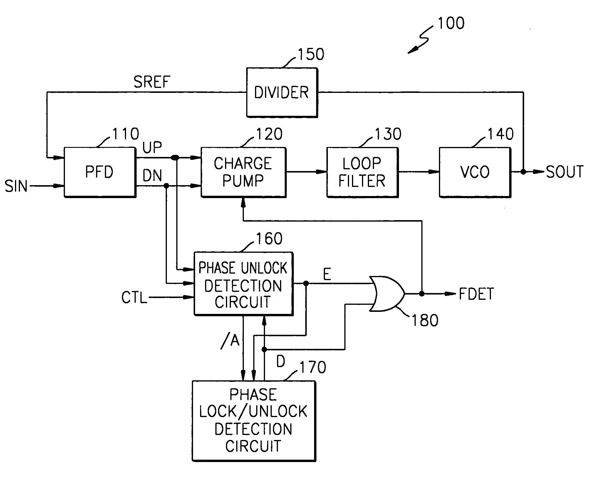
[0036] FIG. 4 is a block diagram of a Phase Locked Loop (PLL) with an improved phase lock / unlock detection function, according to an exemplary embodiment of the present invention.

[0037] Referring to FIG. 4, a PLL 100 includes a Phase Frequency Detector (PFD) 110, a charge pump 120, a loop filter 130, a Voltage Controlled Oscillator (VCO) 140, a divider 150, a phase unlock detection circuit 160, a phase lock / unlock detection circuit 170, and an output circuit 180.

[0038] The PFD 110 compares a phase and frequency of an input synchronization signal SIN to that of a reference synchronization signal SREF and generates an up signal UP or a down signal DN.

[0039] The charge pump 120 controls a charge or discharge of the loop filter 130 according to the up signal UP or down signal DN. The output frequency of the VCO 140 is determined according to a loop voltage from the loop filter 130. The VCO 140 outputs a predetermined clock pulse signal SOUT with a frequency determined by the loop voltag...


PUM


Abstract

There is provided a phase locked loop (PLL) having an improved phase unlock detection function. The PLL generates a clock pulse signal at a frequency from a synchronization signal of a cathode ray tube (CRT) monitor. The PLL includes a phase frequency detector (PFD), a charge pump, a loop filter, a Voltage Controlled Oscillator (VCO), a divider, a phase unlock detection circuit, a phase lock/unlock detection circuit, and an output circuit. The PFD compares a phase and frequency of a synchronization signal to that of a reference signal, and outputs an up or down signal. The charge pump outputs a pumping current in response to the up or down signal. The loop filter outputs a control voltage according to the pumping current. The VCO outputs a clock pulse signal having a frequency determined by a control voltage. The divider divides the clock pulse signal by a division ratio and outputs a reference signal. The phase unlock detection circuit detects an initial generation of a phase unlock from the up or down signal, outputs a first detection signal, and outputs an internal control signal according to the up or down signal. The phase lock/unlock detection circuit outputs a second detection signal, in response to the internal control signal and the first detection signal. The output circuit performs a logic operation on the first detection signal and the second detection signal and outputs a third detection signal. Therefore, the PLL having the improved phase lock/unlock detection function can improve system stability in mode switching of a CRT monitor, by quickly detecting an initial generation of phase unlock without a time delay.

Description

[0001] 1. Technical Field[0002] The present invention relates to a Phase Locked Loop (PLL), and more particularly to a PLL with an improved phase lock / unlock detection function.[0003] 2. Discussion of the Related Art[0004] A Cathode Ray Tube (CRT) monitor is a representative example of the peripheral equipment used with a computer for displaying video signals (e.g., R, G, B) on a screen, according to a horizontal synchronization signal H_Sync and a vertical synchronization signal V_Sync transmitted from a video card of the computer.[0005] When the mode of the CRT monitor switches or power is turned on or off, a transient phenomena occurs in which the frequencies of the horizontal synchronization signal H_Sync and vertical synchronization signal V_Sync vary significantly. This transient phenomena typically induces a surge voltage, resulting in a voltage that can destroy components such as diodes, transistors, etc.[0006] An example of the mode being switched in a CRT monitor is when t...

Claims


Application Information

Patent Timeline
IPC IPC(8): H03L7/089H03L7/095H03L7/08H04N5/12
CPCH03L7/0891H04N5/123H03L7/095H03L7/08
Inventor LEE, JAE-HOON
Owner SAMSUNG ELECTRONICS CO LTD
Why Eureka
Try Eureka