
Dual-capacity insufflator tube

a technology of insufflator tube and insufflator tube, which is applied in the direction of medical insufflators, other medical devices, and infections, can solve the problems of limiting the infusion rate of insufflation gas, difficult to achieve this rate, and difficult to infuse insufflation gas at the desired higher flow ra

Inactive Publication Date: 2004-08-05
NORTHGATE TECH
View PDF3 Cites 24 Cited by
  • Summary
  • Abstract
  • Description
  • Claims
  • Application Information

AI Technical Summary

Benefits of technology

[0011] Another aspect of the invention includes an insufflation system. The insufflation systems includes an insufflator having a delivery assembly for delivering insufflating gas from a pressurized source of insufflation gas to at least one gas delivery path. At least one output line is coupled to the at least one gas delivery path. At least one multi-capacity tube has a first tube with a first end coupled to the at least one output line and a second end. The multi-capacity tube has at least two tubes that each has a first end attached with the second end of the first tube and a second end. At least one spike port is attached with the second end of one of the at least two tubes. The spike port prevents the flow of insufflation gas through the attached one of the at least tube tubes until the at least one spike port is opened. The multi-capacity tube provides for fluid communication of the insufflating gas between the insufflator and laparoscopic equipment that is insertable into a peritoneal cavity.

Problems solved by technology

Achieving this rate, however, often is difficult.
One of the primary limitations in providing higher flows of insufflation gas are the constraints placed upon the insufflation equipment by both common industry practice, efficacy requirements, and guidance documents issued by the United States Food and Drug Administration concerning issues such as push pressures, pressure duration, overshoot, and pressure relief.
This limitation makes it very difficult to infuse insufflation gas at the desired higher flow rates.
Furthermore, the equipment associated with laparoscopic procedures, including the use of standard single PVC tubing, sub-micron filters, and standard laparoscopic equipment such as fixed and rotating collar luers, verres needles, and trocars further restrict the infusion rate of the insufflation gas.
This type of insufflator, however, requires an insufflator capable of creating and controlling separate flow paths within the insufflator, and as a result increases the costs and complexity associated with the insufflator.
This type of insufflator, however, requires the use of much larger, non-standard tubing.
Also, non-standard, large-opening, expensive trocars and or verres needles are required.
Presently, these are not readily available or are not disposable as are the instruments currently in use.

Method used


Image

  • Dual-capacity insufflator tube
  • Dual-capacity insufflator tube
  • Dual-capacity insufflator tube

Examples


Embodiment Construction

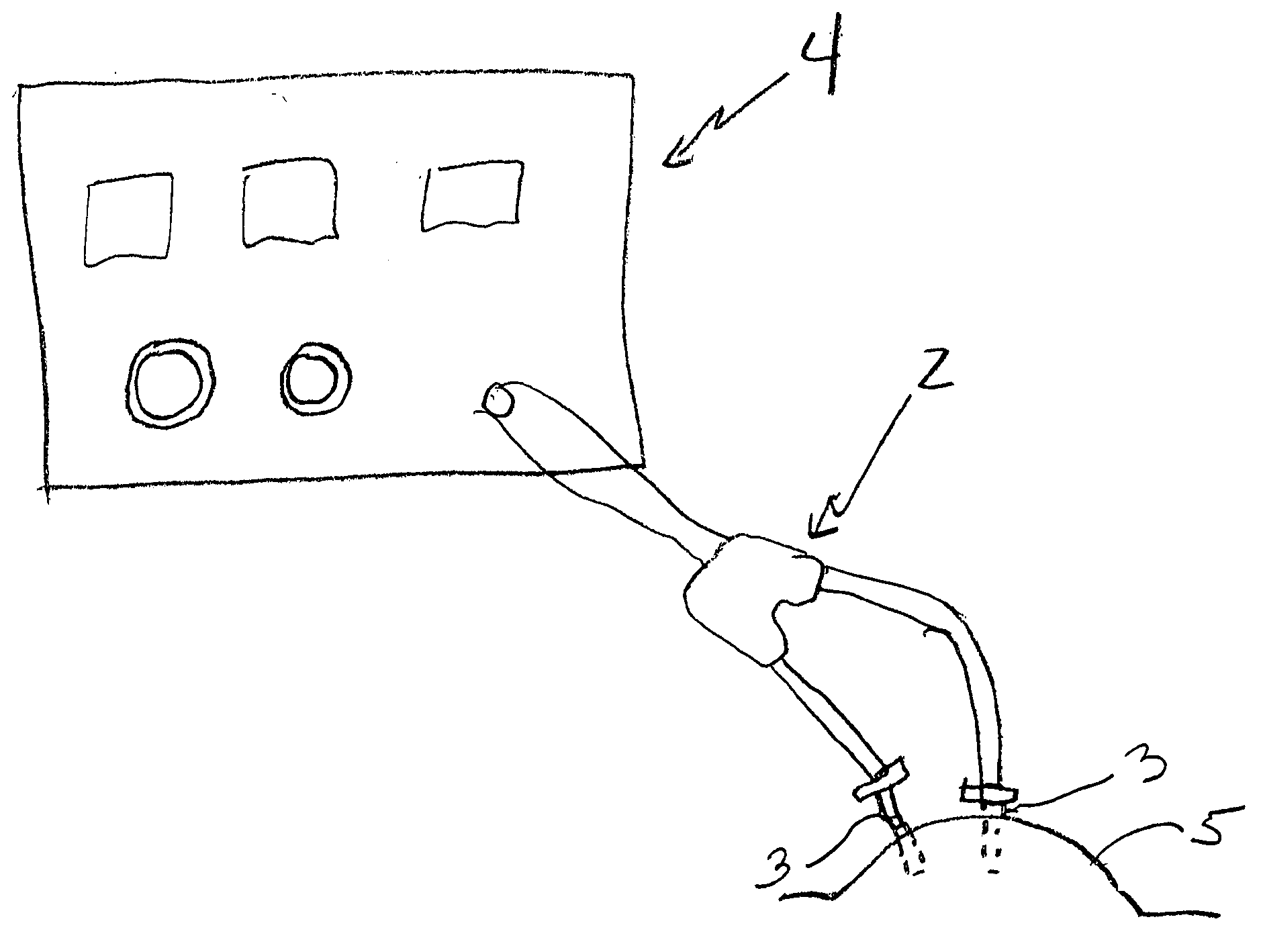
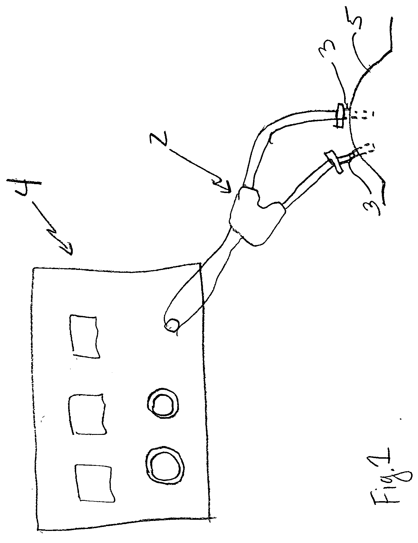
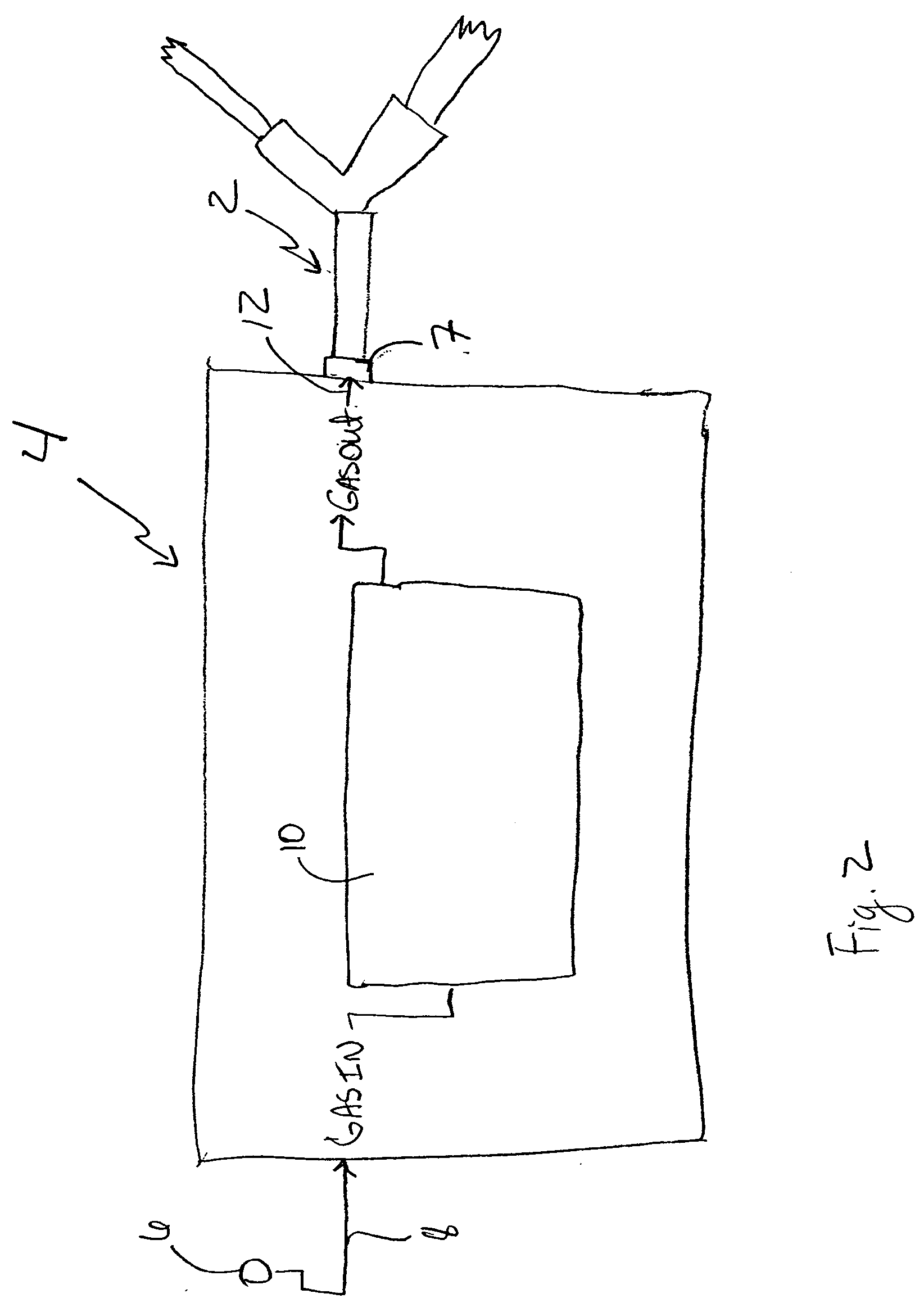
[0022] Referring to FIGS. 1 and 2, an embodiment of a dual-capacity tube 2 attached to an insufflator 4 is shown. As will be discussed further below, the dual-capacity tube 2 provides for the fluid communication of an insufflating gas between the insufflator 4 and laparoscopic equipment 3 that is inserted into a peritoneal cavity 5.

[0023] The insufflator 4 is a standard insufflator, such as the OMNIFLATOR Model 6620 available from Northgate Technologies, Inc. in Elgin, Ill. The insufflator 4 includes a pressurized source 6 of insufflation gas 8. Examples of insufflation gases 8 include, but are not limited to, carbon dioxide, nitrous oxide, argon, or helium. The insufflation gas 8 is reduced in pressure by the insufflator to approximately 45 through 55 millimeters of mercury (also known as a "push" pressure), although the pressure may be changed depending on the insufflator in use and any regulations that may be in force. The insufflation gas 8 is delivered via a delivery assembly 1...


PUM


Abstract

An insufflation system is provided that includes an insufflator having a delivery assembly for delivering insufflating gas from a pressurized source of insufflation gas to at least one gas delivery path. At least one output line is coupled to the at least one gas delivery path. At least one dual-capacity tube has a first tube with a first end coupled to the at least one output line and a second end. The dual-capacity tube has a pair of tubes that each has a first end attached with the second end of the first tube. The dual-capacity tube provides for fluid communication of the insufflating gas between the insufflator and laparoscopic equipment that is insertable into a peritoneal cavity.

Description

[0001] This application claims the benefit of U.S. Provisional Application No. 60 / 421,662, filed Oct. 28, 2002, the entirety of which is incorporated by reference.[0002] The present invention relates to the field of surgical instruments, and in particular, relates to the technology and instrumentation used to achieve pneumoperitoneum during laparoscopy and laparoscopic surgery.[0003] Surgeons have used laparoscopic surgery to perform a variety of procedures. By manipulating laparoscopes and video telescopes, surgeons gain a visualization of the abdominal cavity while minimizing tissue and muscle injury that normally accompanies conventional invasive procedures. Compared to conventional surgery, laparoscopy reduces patient trauma, decreases patient recovery time, and yields significant cost savings by reducing post-operative care.[0004] The proper hardware and instrumentation are essential to the performance of laparoscopic procedures. To create a sufficient area for the introduction...

Claims


Application Information

Patent Timeline
IPC IPC(8): A61LA61M37/00
CPCA61M13/003A61M16/202A61M2205/7536A61M16/208A61M2205/7545A61M16/0816A61M16/0833A61M16/209
Inventor MANTELL, ROBERT R.
Owner NORTHGATE TECH
Learn More