
Rod connector assembly

a technology of connectors and rods, applied in the direction of rod connections, couplings, manufacturing tools, etc., can solve the problems of reducing the useful life of conventional valve stem connectors, affecting the service life of the connector, so as to reduce friction

Inactive Publication Date: 2004-08-12
FISHER CONTROLS INT LLC
View PDF9 Cites 25 Cited by
  • Summary
  • Abstract
  • Description
  • Claims
  • Application Information

AI Technical Summary

Benefits of technology

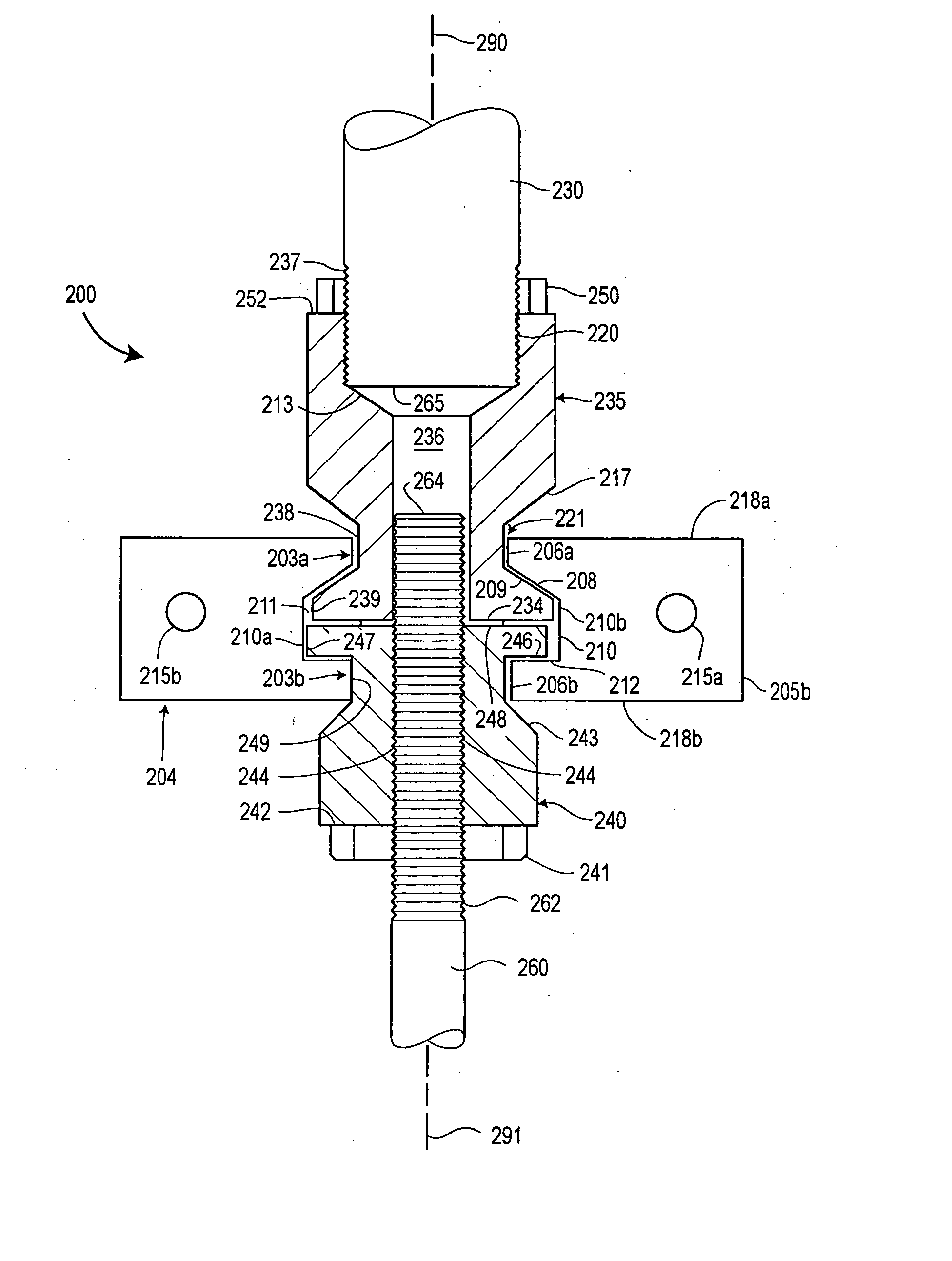
[0012] Accordingly, it is the object of the present rod connector assembly to provide a connector device that can accommodate axial misalignment between the two rods, conveniently compensate for various lengths of rods and that can prevent substantial rotation of two rods about their respective common axis. Further, the present rod connector significantly reduces the friction created by asymmetric side loads exerted by a valve stem upon valve packing that would otherwise occur in a control valve assembly.
[0013] In accordance with one aspect of the present rod connector assembly, a first rod assembly having a tapered clamping surface and a second rod assembly both having generally planar end surfaces are fastened by a rod union that loads the tapered clamping surface to mechanically couple the first and second rod assemblies. A shaped internal cavity within the rod union forms an upper and lower rim to engage correspondingly shaped mating surfaces on the rod assemblies together. The shaped cavity further forms clearance surfaces that accommodate axial misalignment of the first and second rods and prevents rotation of the rod assemblies relative to each other.
[0016] In a further embodiment, a method for reducing the friction between a valve stem assembly and valve packing is established.

Problems solved by technology

Conventional valve stem connectors suffer certain manufacturing disadvantages and design limitations as described below.
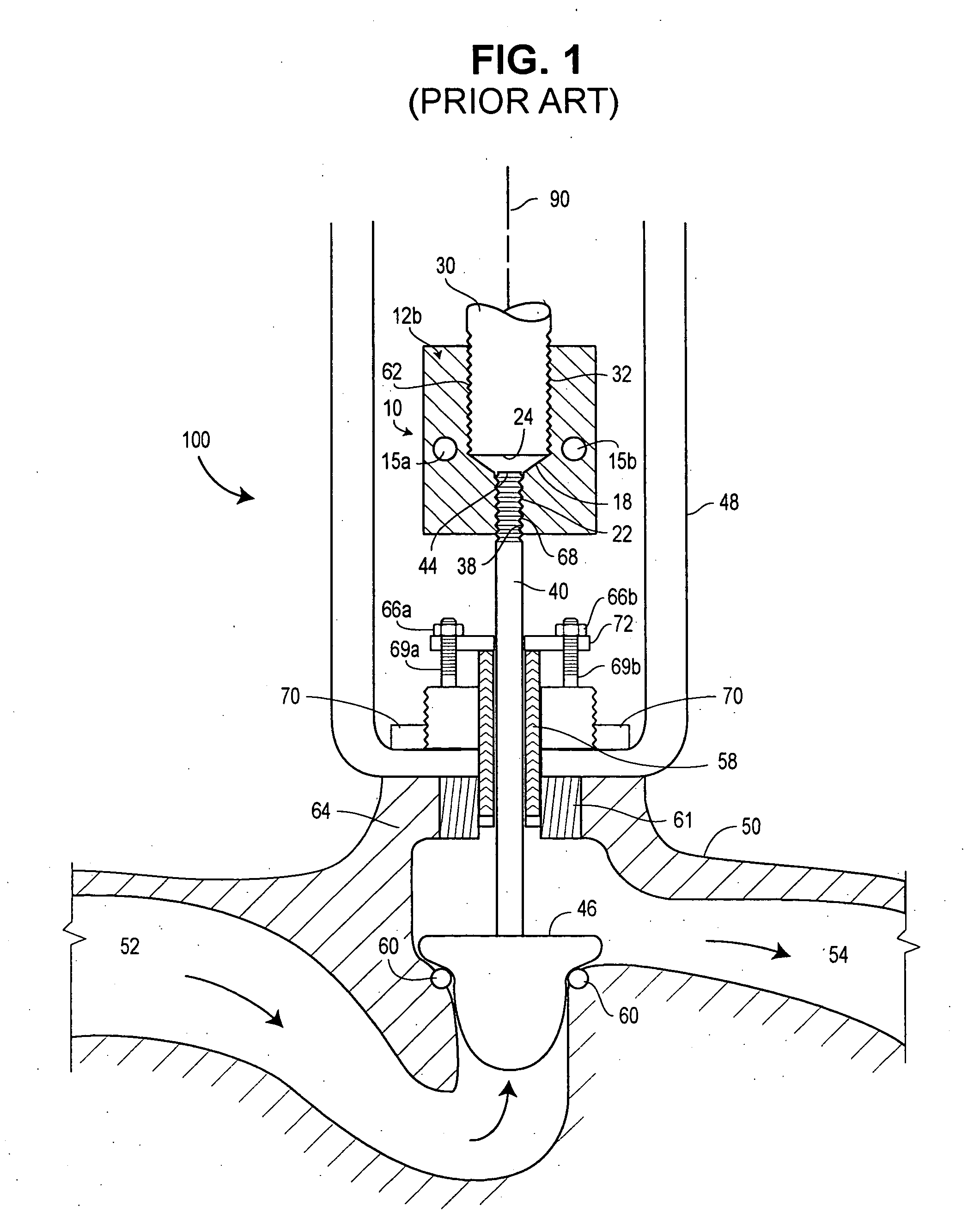
Accordingly, any asymmetric forces exhibited by the valve stem 40 upon the valve packing 58 can increase packing friction through the region of asymmetric force causing degradation and erosion of the valve packing 58 and substantially reduce its useful life.
The presence of these asymmetric forces can increase maintenance costs and can increase the risk of environmental hazards if the fluids escape to the surrounding atmosphere.
In the opposite direction, the adjustment limitation is based on a minimum number of threads that must be engaged to create a secure and safe mechanical connection.
The narrow manufacturing tolerances result in higher manufacturing costs and increased assembly difficulty.

Method used


Image

  • Rod connector assembly
  • Rod connector assembly
  • Rod connector assembly

Examples


Embodiment Construction

[0029] To fully appreciate the advantages of the disclosed rod connector assembly, its functions and features are described in connection with an actuator rod and valve stem. However, one skilled in the art would appreciate the present rod connector assembly could be used in other rod connector applications.

[0030] Referring now to FIGS. 3A and 3B, a fundamental component of the improved valve stem connector, a stem union 204, is separately illustrated. The stem union 204 is fashioned by fastening two approximately equal connector halves 205a-b together forming a connector to mechanically bind the actuator rod 230 to the valve stem 260 (shown cross-sectionally in FIG. 4). When joined, the connector halves 205a-b create a shaped internal cavity 211 having two openings 203a-b. The shaped internal cavity 211 includes a plurality of vertical walls 210 and has a larger cross section than the openings 203a-b to provide an upper flange 206a and a lower flange 206b within the stem union 204....


PUM

PropertyMeasurementUnit
angleaaaaaaaaaa
angleaaaaaaaaaa
diameteraaaaaaaaaa

Abstract

An improved rod connector assembly and method for mechanically fastening two rods together. Generally planar mating surfaces of a first rod assembly and a second rod assembly are compressively coupled by a rod union. The compressive load by the rod union is derived from a tapered surface that provides an interference fit to a corresponding tapered surface on the first rod assembly. Clearance diameters provided within the rod union accommodate axial misalignment of the first rod assembly and the second rod assembly. The second rod assembly includes an adjustable rod adapter to provide coupling to rods of various lengths. The first rod assembly includes an internal cavity to receive a portion of the second rod that may protrude from the adjustable rod adapter. Shaped mating surfaces of the rod adapters are received in a corresponding shaped cavity of the union to prevent rotation of the adapters.

Description

[0001] This is a continuation-in-part of U.S. application Ser. No. 10 / 360,668, filed on Feb. 7, 2003, which is incorporated herein by reference.[0002] The rod connector assembly described herein makes known an apparatus and method for mechanically fastening two rods together. More specifically, a valve stem connector and method for fastening an actuator rod to a control valve stem is disclosed. The present rod connector assembly significantly reduces the asymmetric forces exerted by the valve stem on the valve packing due to axial misalignment of the actuator rod and the valve stem.BACKGROUND OF THE RELATED ART[0003] Control valves are typically operated by pneumatic actuators, such as spring and diaphragm actuators, that are directly coupled to the valve. The pneumatic actuator provides the force necessary to move a valve plug to control a fluid flowing through the valve. As understood by those skilled in the art, increasing or decreasing the air pressure within a pressure chamber ...

Claims


Application Information

Patent Timeline
Patent Type & Authority Applications(United States)
IPC IPC(8): F16B7/04F16K1/48
CPCF16B7/0426F16K1/48Y10T403/75Y10T403/5746Y10T403/7062F16K31/126B29C63/34F16L55/1654
Inventor MCCARTY, MICHAEL W.
Owner FISHER CONTROLS INT LLC
Learn More