High-voltage discharge lamp lighting apparatus, high-voltage discharge lamp apparatus, and floodlight projector apparatus
a technology of high-voltage discharge and lighting apparatus, which is applied in the direction of cathode-ray/electron beam tube circuit elements, instruments, and coupling device connections, etc., can solve the problems of increased replacement costs of high-voltage discharge lamps, danger of electric shock, etc., and achieves the suppression of reducing the leakage of high-voltage energy
- Summary
- Abstract
- Description
- Claims
- Application Information
AI Technical Summary
Benefits of technology
Problems solved by technology
Method used
Image
Examples
first embodiment
[0090] Hereinbelow, the present invention will be described with reference to FIGS. 1, 2A, and 2B.
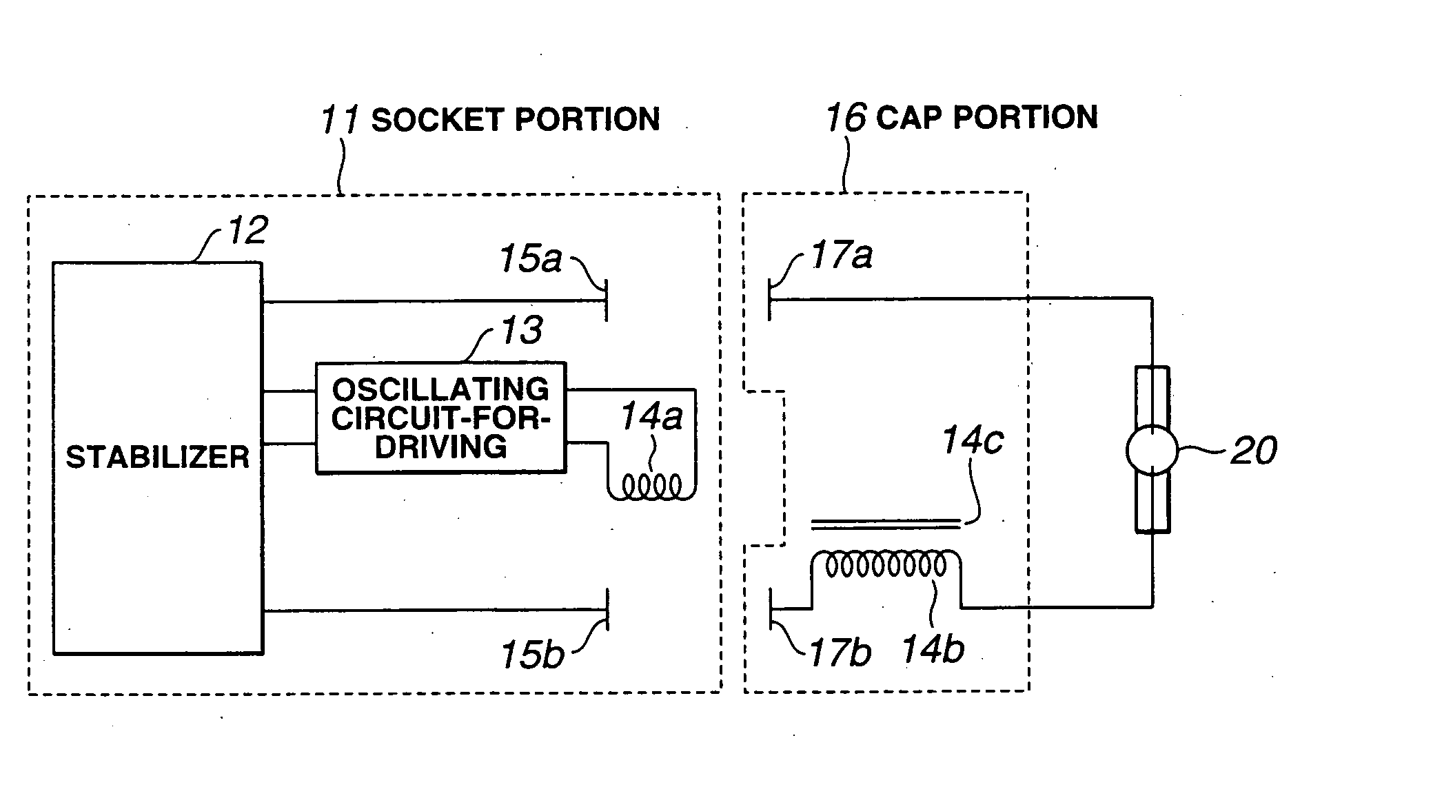
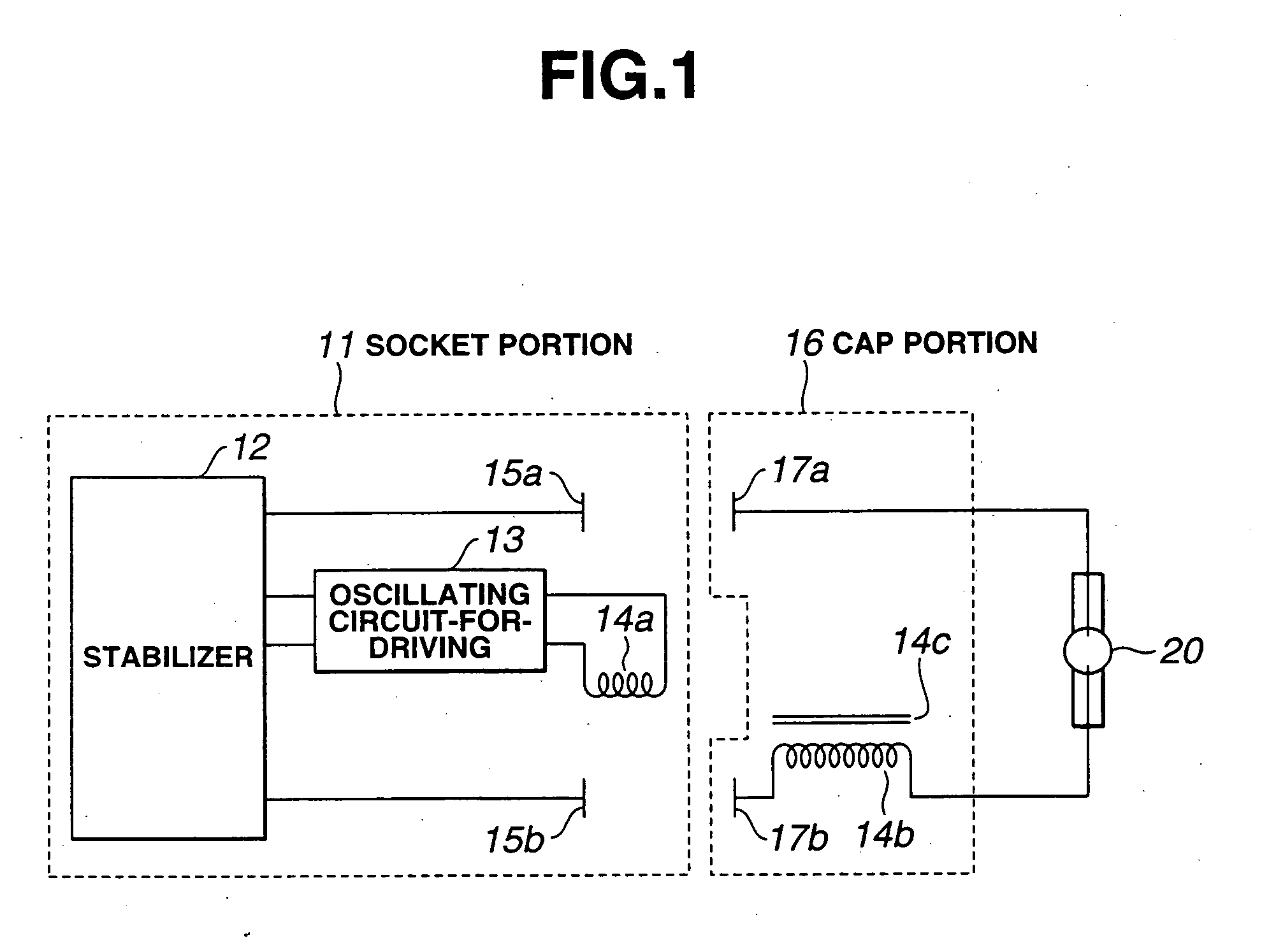
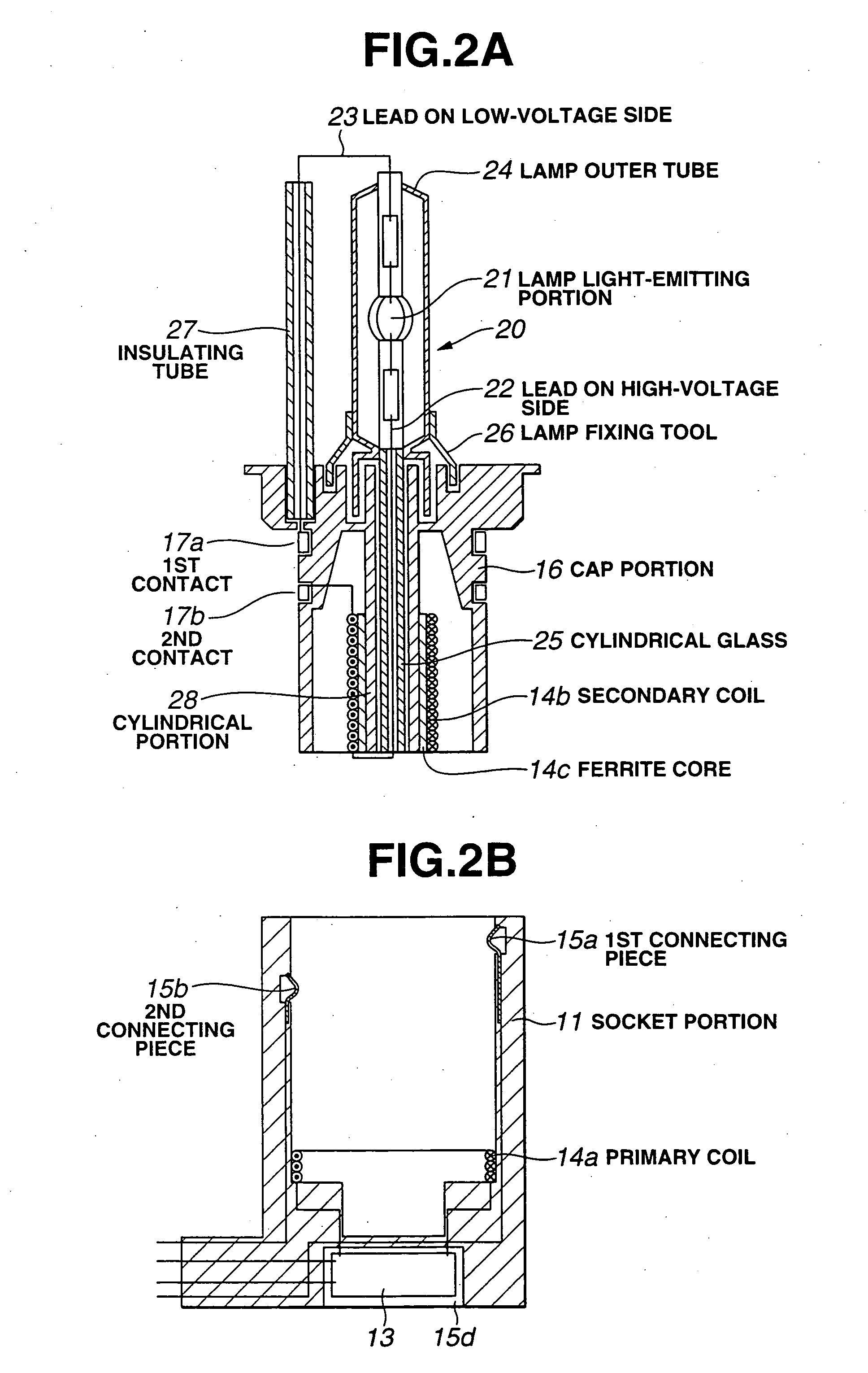
[0091] FIG. 1 is a block diagram of showing the structure of a high-voltage discharge lamp lighting apparatus according to the first embodiment of the present invention, FIG. 2A is a sectional view for explaining the structure of a cap portion used for the high-voltage discharge lamp lighting apparatus according to the first embodiment of the present invention, and FIG. 2B is a sectional view for explaining the structure of a socket portion to which the cap portion shown in FIG. 2A is fit and attached. Here, a description is given of a lighting apparatus of a headlight lamp for automobile as the high-voltage discharge lamp lighting apparatus of the present invention.
[0092] The high-voltage discharge lamp lighting apparatus shown in FIG. 1 is in a state before fitting and attaching the cap portion 16 to the socket portion 11. By fitting and attaching the cap portion 16 to the socket port...
second embodiment
[0124] Referring to FIG. 3A, according to the present invention, the socket portion 11 comprises: the stabilizer 12; the oscillating circuit-for-driving 13 which generates a high-frequency oscillating voltage based on the DC power voltage from the stabilizer 12; the primary coil 14a and the ferrite core 14c of the high-voltage pulse transformer 14 to which the high-frequency oscillating voltage generated by the oscillating circuit-for-driving 13 is supplied. Further, the socket portion 11 has the first connecting piece 15a and the second connecting piece 15b which output the power voltage necessary for maintaining the lighting operation from the stabilizer 12.
[0125] The cap portion 16 comprises: the secondary coil 14b of the high-voltage pulse transformer 14; the second contact 17b for connection to one electrode of the high-voltage discharge lamp 20 via the secondary coil 14b; and the first contact 17a for connection to another electrode of the high-voltage discharge lamp 20.
[0126]...
third embodiment
[0138] Referring to FIG. 3B, the high-voltage discharge lamp lighting apparatus comprises the cap portion 16 and the socket portion 11 as shown in FIGS. 4A and 4B. Referring to FIGS. 4A and 4B, the same portions as those shown in FIGS. 2A and 2B are designated by the same reference numerals and a detailed description is omitted.
[0139] Referring to FIG. 4B, the socket portion 11 comprises the primary coil 14a, the secondary coil 14b, and the magnetic core 14c of the high-voltage pulse transformer 14. One output terminal from the stabilzier 12 is connected to the first connecting piece 15a and a terminated end of the primary coil 14a is connected to the third connecting piece 15c in the socket portion 11. A terminated end of the secondary coil 14b is connected to the connecting piece 15b' on the high-voltage side in the center of the bottom portion of the socket portion 11.
[0140] Referring to FIG. 4A, a first contact 17a is arranged to the cap portion 16 like strips so as to connect ...
PUM
 Abstract
Description
Claims
Application Information
 - R&D
- Intellectual Property
- Life Sciences
- Materials
- Tech Scout
- Unparalleled Data Quality
- Higher Quality Content
- 60% Fewer Hallucinations
Browse by: Latest US Patents, China's latest patents, Technical Efficacy Thesaurus, Application Domain, Technology Topic, Popular Technical Reports.
© 2025 PatSnap. All rights reserved.Legal|Privacy policy|Modern Slavery Act Transparency Statement|Sitemap|About US| Contact US: help@patsnap.com


