Servo motor control system

a technology of servo motors and control systems, applied in the direction of program control, dynamo-electric converter control, instruments, etc., can solve the problems of system failure to operate, and inability to establish communication between numerical control devices and servo amplifiers

Active Publication Date: 2004-08-19
FANUC LTD
View PDF11 Cites 44 Cited by
  • Summary
  • Abstract
  • Description
  • Claims
  • Application Information

AI Technical Summary

Problems solved by technology

When bit rates in serial communication between the numerical control device and the servo amplifiers or between the servo amplifiers are different from each other, communication between the numerical control device and the servo amplifiers or between the servo amplifiers cannot ...

Method used


Image

  • Servo motor control system
  • Servo motor control system
  • Servo motor control system

Examples


first embodiment

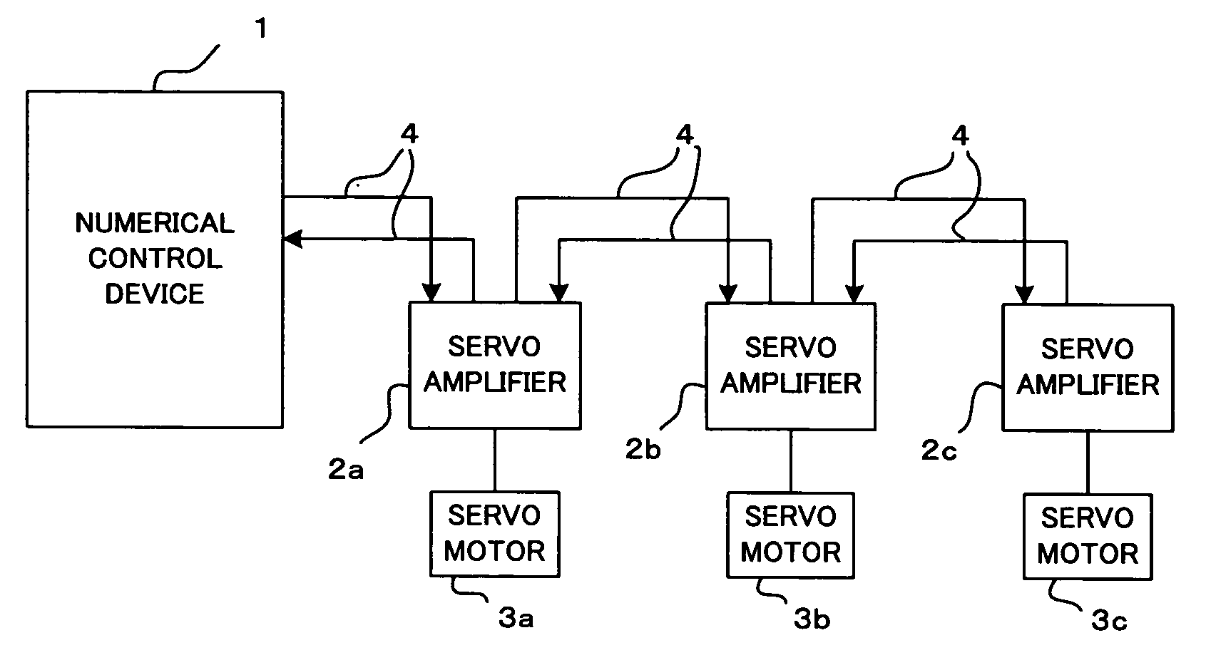
[0040] According to the first embodiment, a data transfer system which is set as a parameter in the numerical control device 1 in advance is used. In order to change the data transfer system, a common data transfer can be established to the numerical control device 1 and the servo amplifiers 2a to 2c by only changing the set parameter. In the first embodiment, when a system is constructed, or when the numerical control device or the servo amplifiers are partially replaced with new one, bit rates of the data transfer system which can be used by the numerical control device 1 and the servo amplifiers 2a to 2c carrying out communication are set as parameters.

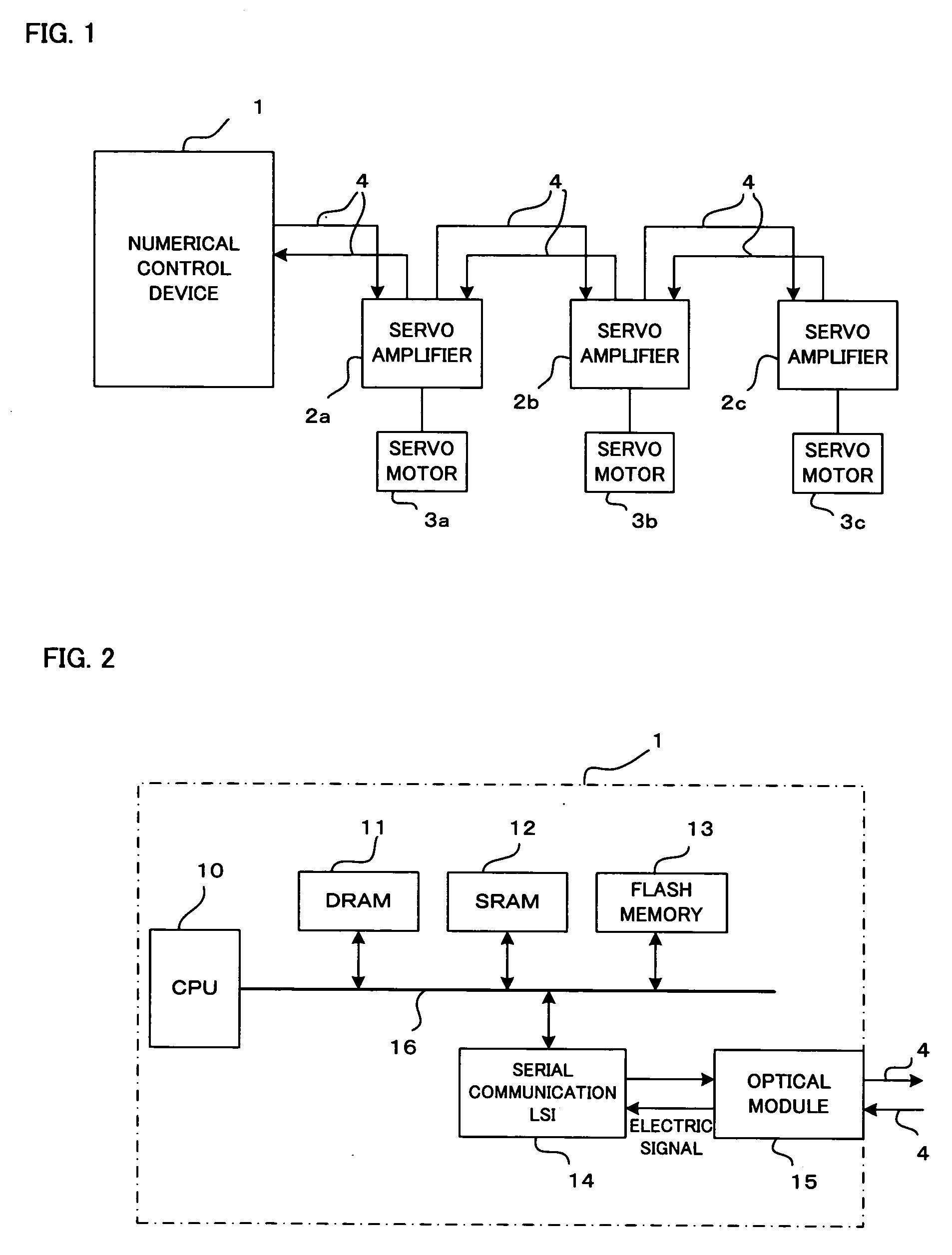
[0041] When the system is powered on and reset, the serial communication LSI 14 of the numerical control device 1 transmits a signal called an idle pattern in which high and low levels alternately appear, which is the same signal as a clock signal having a frequency being 1 / 2 the lowest bit rate, to the optical cable 4 through the ...

second embodiment

[0045] According to the second embodiment, a common data transfer system is automatically set in a numerical control device 1 and all servo amplifiers 2a to 2c by the numerical control device 1.

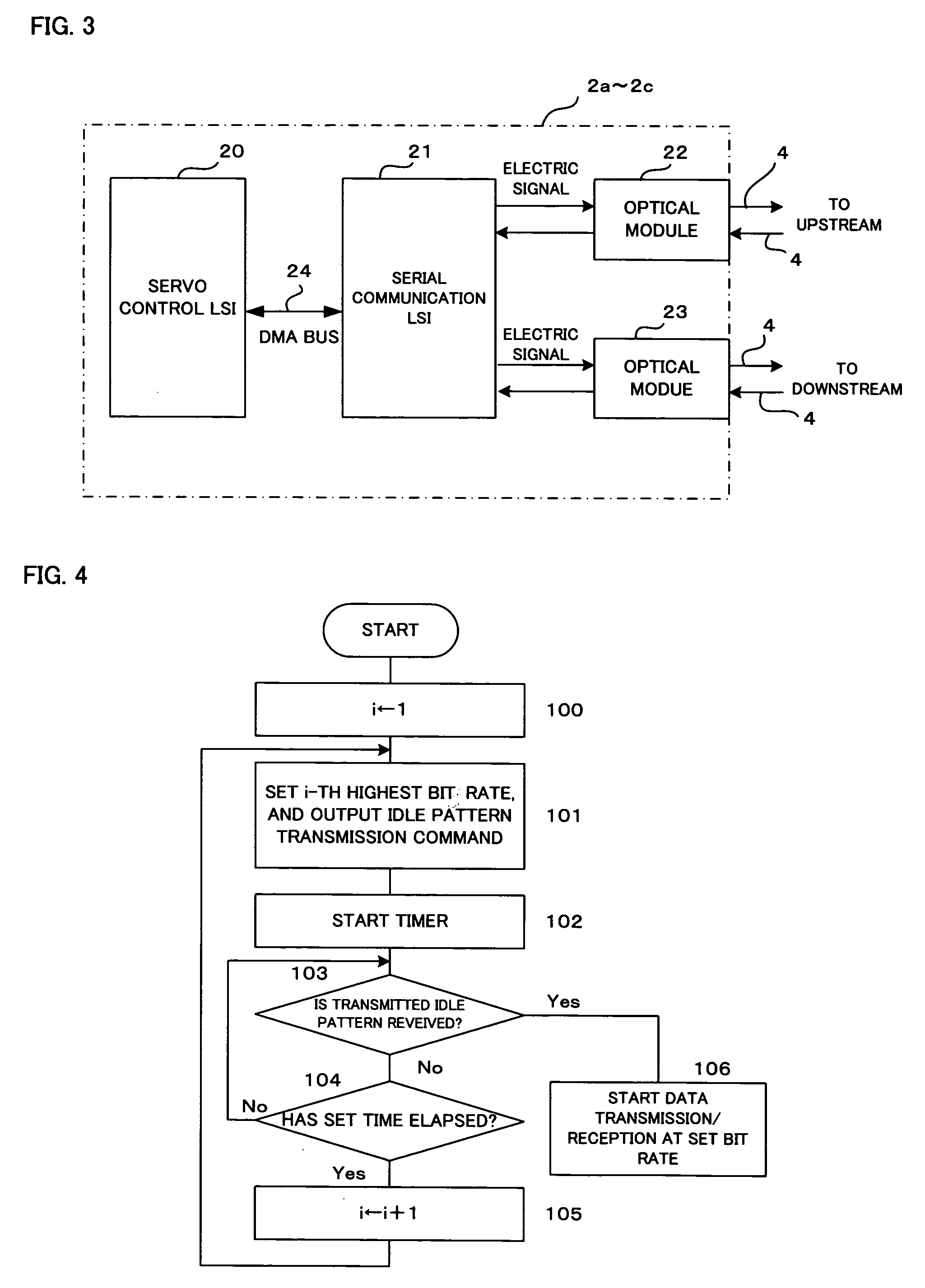
[0046] When the system is powered on and reset, the serial communication LSI 14 of the numerical control device 1 transmits an idle pattern having the lowest bit rate to the servo amplifier 2a. Each servo amplifier transmits an idle pattern having the lowest bit rate to the downstream servo amplifier, and the most downstream servo amplifier 2c transmits the idle pattern to an upstream servo amplifier, and sequentially transmits the idle pattern to further upstream servo amplifiers. The numerical control device 1 receives the idle pattern having the lowest bit rate.

[0047] When the reset signal is canceled, as described above, the numerical control device 1 loads a system program from a flash memory 13 so that the system program is developed on a DRAM 11, and then executes the developed system ...


PUM


Abstract

In a servo control system, a numerical control device and at least one servo amplifier are connected to each other with a serial bus to control a servo motor connected to the servo amplifier. In this system, data transfer systems of at least two types for the serial bus are set, and a data transfer system is selected by a parameter set in the numerical control device.

Description

[0001] 1. Field of the Invention[0002] The present invention relates to a servo motor control system for controlling servo motors for shafts in machines such as various industrial machines, machine tools, and robots.[0003] 2. Description of the Related Art[0004] In a servo motor control system, a numerical control device and servo amplifiers for driving and controlling servo motors are connected to each other with a serial bus, and the numerical control device exchanges data used to control the servo motors with the servo amplifiers through the serial bus. As a connection system between the numerical control device and the servo amplifiers with a serial bus, a daisy chain system achieved by an optical cable is known (for example, see Japanese Unexamined Patent Publication No. 10-13394).[0005] When bit rates in serial communication between the numerical control device and the servo amplifiers or between the servo amplifiers are different from each other, communication between the num...

Claims


Application Information

Patent Timeline
IPC IPC(8): G05B19/408G05B9/03
CPCG05B19/408G05B2219/31174G05B2219/33226G05B2219/33214G05B2219/33187
Inventor KOMAKI, KUNITAKAAIZAWA, YASUHARUAOYAMA, KAZUNARI
Owner FANUC LTD
Why Eureka
Try Eureka