Magnetic tape

a technology of magnetic tape and tape, applied in the field of magnetic tape, can solve the problems of reducing tracking accuracy, reducing the shrinkage ratio, and not being able to meet the form stability of metal-evaporated tap

Inactive Publication Date: 2004-08-26
SONY CORP
View PDF14 Cites 1 Cited by
  • Summary
  • Abstract
  • Description
  • Claims
  • Application Information

AI Technical Summary

Benefits of technology

[0022] According to the present invention, the magnetic tape is fabricated so that the heat-shrinkage ratio in the longitudinal direction and the width direction is 0.50% or less and the humidity expansion factor is 1.times.10.sup.-6 / % RH or less after stock at 100.degree. C. and 5% RH for 30 minutes. As a result, the magnetic tape having little form deformation even after long-term stock or in use at a high humidity and therefore having little decrease in reproduction output, can be obtained.

Problems solved by technology

As a result of the studies made by the inventor of the present invention, however, it is found that the metal-evaporated tape is not still satisfactory in terms of form stability in the case where it is used as a conventional magnetic tape for computer data recording.
Even in the case where the metal-evaporated tape is used for conventional computer data recording, a shrinkage ratio is relatively large.
Therefore, if recording / reproduction is performed on / from this tape, it is found that tracking accuracy is lowered.
If too large, the reinforcement by the magnetic layer 2 or the protective layer 3 is not sufficient, resulting in a large heat-shrinkage ratio or humidity expansion coefficient.
As a result, the recording tape stock characteristics are degraded.
If the thickness of the magnetic layer 2 is too small, the reinforcement for the nonmagnetic support 1 is not sufficient, preventing the heat-shrinkage ratio or the humidity expansion coefficient of the entire tape from being kept within the above range.

Method used


Image

  • Magnetic tape
  • Magnetic tape
  • Magnetic tape

Examples


example 2

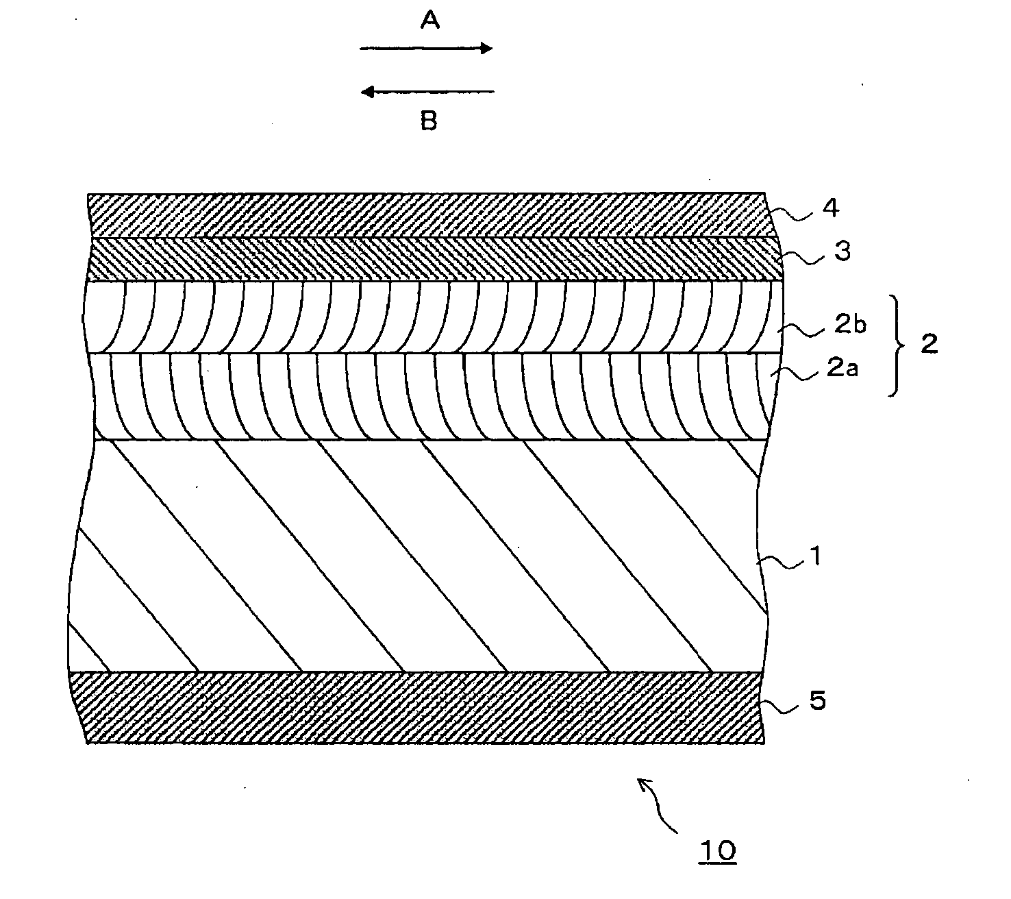
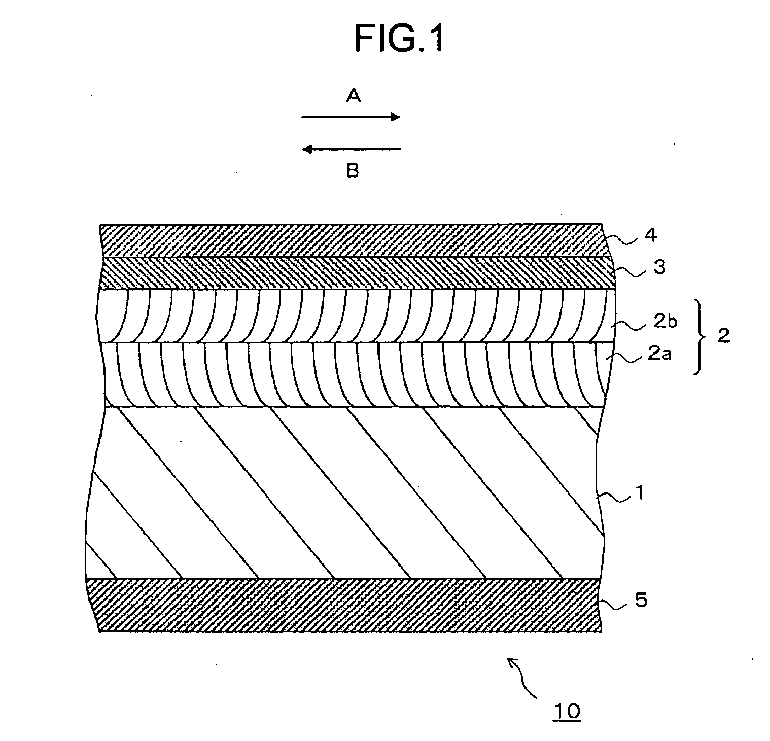
[0071] The magnetic tape was fabricated in the same manner as in Example 1 except that the thickness of the lower-layer magnetic thin film 2a was 15 nm and the thickness of the upper-layer magnetic thin film 2b was 10 nm, that is, the total thickness of the magnetic layer 2 was 25 nm. The heat-shrinkage ratio of the magnetic tape was 0.25%, and the humidity expansion coefficient was 0.5.times.10.sup.-6 / % RH.

example 3

[0072] The magnetic tape was fabricated in the same manner as in Example 1 except that the thickness of the lower-layer magnetic thin film 2a was 50 nm and the thickness of the upper-layer magnetic thin film 2b was 25 nm, that is, the total thickness of the magnetic layer 2 was 75 nm. The heat-shrinkage ratio of the magnetic tape was 0.1%, and the humidity expansion coefficient was 0.3.times.10.sup.6 / % RH.

example 4

[0073] The magnetic tape was fabricated in the same manner as in Example 1 except that the thickness of the nonmagnetic support 1 was 6 .mu.m. The heat-shrinkage ratio of the magnetic tape was 0.2%, and the humidity expansion coefficient was 0.4.times.10.sup.-6 / % RH.


PUM


Abstract

A magnetic tape having a small degree of deformation, high form stability and little decrease in reproduction output even after stock at a high humidity is provided. The magnetic tape includes a longitudinally extending nonmagnetic support, a magnetic layer formed by depositing a plurality of evaporated magnetic films, each having an oblique column-like structure, on a principal surface of the nonmagnetic support so that a growth direction of each of the evaporated magnetic films is opposite to the longitudinal direction, a protective layer formed on the magnetic layer, and a backcoating layer formed on the other surface of the nonmagnetic support, wherein a heat-shrinkage ratio in the longitudinal direction and a width direction is defined to be 0.50% or less and a humidity expansion coefficient at 25° C. is defined to be 1x10<-6> / % RH or less after stock at 100° C. and 5% RH for 30 minutes.

Description

[0001] This application claims priority from Japanese Priority Document No. 2003-042730, filed on Feb. 20, 2003 with the Japanese Patent Office, which document is hereby incorporated by reference.[0002] 1. Field of the Invention[0003] The present invention relates to a magnetic tape, in particular, to a magnetic tape used as an external recording medium for recording data, which includes a magnetic layer composed of evaporated magnetic films.[0004] 2. Description of the Related Art[0005] Recently, along with the diffusion of minicomputers, personal computers or office computers such as work stations, a magnetic tape for recording computer data as an external recording medium (a so-called backup tape) has been actively studied.[0006] For practical use of such a magnetic tape for data storage, the increase in storage capacity is highly demanded in relation with, in particular, the miniaturization of computers and the increase in information processability. In addition, with the expans...

Claims


Application Information

Patent Timeline
IPC IPC(8): G11B5/66G11B5/65G11B5/72G11B5/73G11B5/735G11B5/78
CPCG11B5/70G11B5/7305G11B5/716
Inventor NAGAI, NOBUYUKI
Owner SONY CORP
Why Eureka
Try Eureka