
Resin plate

a technology of resin plates and slags, applied in the field of resin plates, can solve problems such as warp wave, difficult surface to work as dull surface, and deformation such as wav

Inactive Publication Date: 2004-09-30
SUMITOMO CHEM CO LTD
View PDF4 Cites 37 Cited by
  • Summary
  • Abstract
  • Description
  • Claims
  • Application Information

AI Technical Summary

Problems solved by technology

The resin plate, however, has problems such that the absorption of moisture in the air thereinto easily causes deformation such as warp and wave.
When the resin plate has a ten-point average roughness (Rz) of less than about 5 .mu.m and / or an average peak distance (Sm) of more than about 300 .mu.m on the at least one surface, it tends to be difficult that the surface works as a dull surface because of directly reflecting incident light.

Method used


Image

  • Resin plate
  • Resin plate
  • Resin plate

Examples


examples 3 to 6

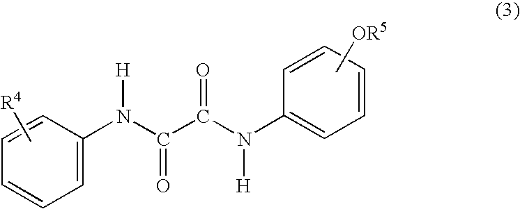
[0135] UVA (2) (0.01 part by weight) and MA resin (100 parts by weight) were mixed with each other by a Henschel mixer and were melt-kneaded by the same first extruder as was used in Example 1 while being heated, whereby obtaining a first melt-kneaded product.

[0136] Meanwhile, 0.015 part by weight of UVA (1) and MA resin and FV resin in the amounts shown respectively in Table 2 were mixed by a Henschel mixer and were melt-kneaded by the same second extruder as was used in Example 1 while being heated, whereby obtaining a second melt-kneaded product.

[0137] In such a manner that the first melt-kneaded product obtained above is made into a base layer and the second melt-kneaded product obtained above is made into surface layers, the first melt-kneaded product and the second melt-kneaded product were supplied from the first extruder and the second extruder to a two-kind two-layer distribution type multi-manifold die [manufactured by TANABE PLASTICS CO., LTD.] respectively so as to be co...

example 7

[0138] A resin plate was obtained by the same process as is Example 6 except for increasing the amount of the second melted resin supplied to the multi-manifold die. This resin plate had a two-layer constitution such that the surface layer was laminated on one surface of the base layer, the surface layer having a thickness of 0.2 mm and the base layer having a thickness of 1.8 mm. The results of evaluating the resin plate are shown in Table 3. A test piece used for measuring a degree of warpage had a size of 20 cm.times.20 cm.

3TABLE 3 MA Resin FV Resin UVA (1) Degree (parts by (parts by (parts by of Warpage Tt weight) weight) weight) (mm) (%) Example 7 60 40 0.015 0.21 93

example 16

[0145] A resin plate having a width of 22 cm, a length of 80 cm and a thickness of 2 mm was obtained by the same process as in Example 13 except for replacing the multi-manifold die with the same two-kind three-layer distribution type feed block die as was used in Example 1. The obtained resin plate had a three-layer constitution such that the surface layers were laminated on both surfaces of the base layer, each of the surface layers having a thickness of 0.03 mm and the base layer having a thickness of 1.94 mm. The results of evaluating the resin plate are shown in Table 8.

8TABLE 8 Degree Tt of Warpage I.sub.5 / I.sub.0 I.sub.70 / I.sub.0 Rz Sm (%) (mm) (%) (%) .DELTA.E (.mu.m) (.mu.m) Example 16 63 0.96 98 18 8.8 3.2 33


PUM

PropertyMeasurementUnit
Percent by massaaaaaaaaaa

Abstract

A resin plate comprising a base layer and a surface layer placed on at least one side of the base layer is provided. The base layer is made from a methyl methacrylate polymer having about 30% by weight or more of a methyl methacrylate unit as a monomer unit, and the surface layer has a thickness of about 5 mum to about 500 mum and is made from a resin composition containing about 40 parts by weight to about 95 parts by weight of a methyl methacrylate resin and about 5 parts by weight to about 60 parts by weight of a vinylidene fluoride resin with respect to 100 parts by weight in total of the methyl methacrylate resin and the vinylidene fluoride resin. The resin plate has a superior transparency and little deformation due to moisture absorption.

Description

[0001] 1. Field of the Invention[0002] The present invention relates to a resin plate. In particular, the present invention relates to a resin plate having a superior transparency and little deformation due to moisture absorption.[0003] 2. Related Art[0004] A methyl methacrylate polymer containing 30% by weight or more of a methyl methacrylate unit as a monomer unit is useful as a resin having a superior transparency. A resin plate obtained by molding the polymer into a plate shape has been directly used, for example, as a light guide plate which is to be disposed on the backside of a liquid crystal display (see, Japanese Patent Application Laid-Open Nos. 10-265530, 59-68333 and 60-13813).[0005] The resin plate, however, has problems such that the absorption of moisture in the air thereinto easily causes deformation such as warp and wave.[0006] The present inventors have studied for developing a resin plate having a superior transparency as well as little deformation due to moisture...

Claims


Application Information

Patent Timeline
IPC IPC(8): B32B27/30B32B27/08C08L23/06C08L23/08
CPCB32B27/30B32B2307/412B32B2333/12C08L23/06C08L23/0815C08L2666/06Y10T428/31855A22C25/04A22C25/08B07B13/04B32B2250/24B32B27/18B32B27/304B32B27/08B32B27/308B32B2551/00B32B2309/105
Inventor MAEKAWA, TOMOHIROMANABE, KENJI
Owner SUMITOMO CHEM CO LTD
Learn More