Pressure sensor diagnosis via a computer

a technology of pressure sensor and computer, which is applied in the direction of fluid pressure measurement, air quality improvement, machine/engine, etc., can solve the problems of dpf regeneration, affecting driveability, or being too frequent or too infrequen

Inactive Publication Date: 2004-10-14
FORD GLOBAL TECH LLC
View PDF11 Cites 60 Cited by
  • Summary
  • Abstract
  • Description
  • Claims
  • Application Information

AI Technical Summary

Benefits of technology

0027] Thus, according to the present invention, it is possible to monitor a sensor whose failure m

Problems solved by technology

Specifically, if the pressure sensor is used to control regeneration is degraded, this can result in either too frequent, or too infrequent, DPF regeneration.
Too frequent regeneration (from an erroneously high reading) can result in decreased fuel economy as energy is needlessly spent raising exhaust gas temperatu

Method used


Image

  • Pressure sensor diagnosis via a computer
  • Pressure sensor diagnosis via a computer
  • Pressure sensor diagnosis via a computer

Examples


Embodiment Construction

)

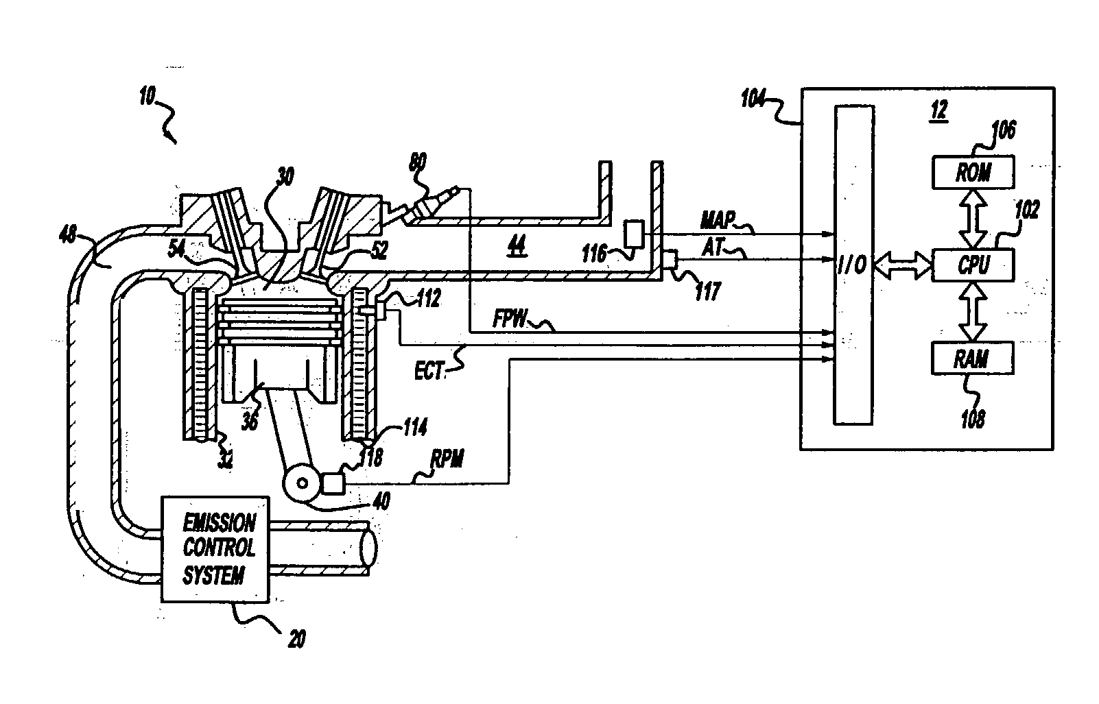
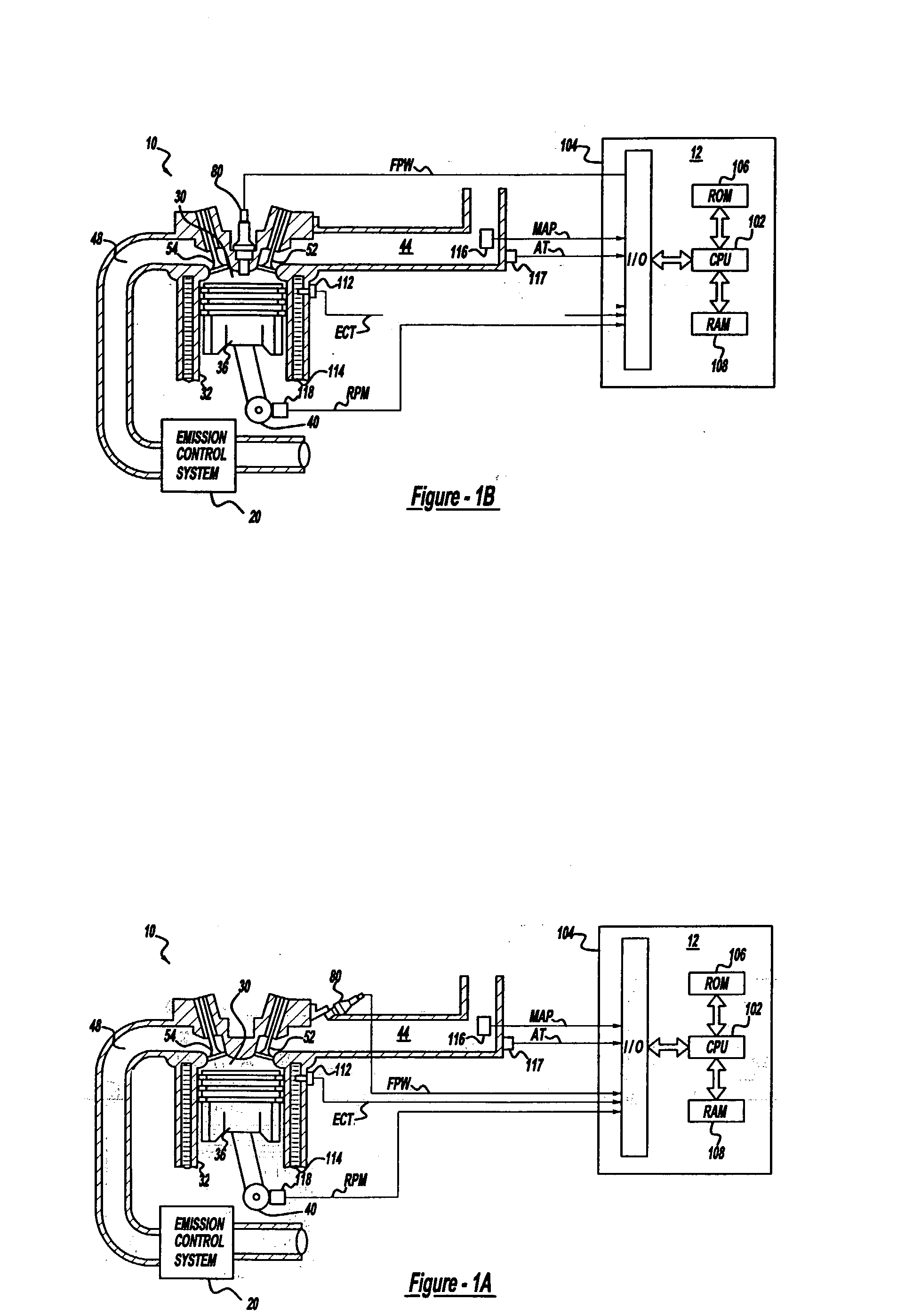
[0036] Internal combustion engine 10, comprising a plurality of cylinders, one cylinder of which is shown in FIG. 1A, is controlled by electronic engine controller 12. Engine 10 includes combustion chamber 30 and cylinder walls 32 with piston 36 positioned therein and connected to crankshaft 40. Combustion chamber 30 is shown communicating with intake manifold 44 and exhaust manifold 48 via respective intake valve 52 and exhaust valve 54. Intake manifold 44 is also shown having fuel injector 80 coupled thereto for delivering liquid fuel in proportion to the pulse width of signal FPW from controller 12. Both fuel quantity, controlled by signal FPW and injection timing are adjustable. Fuel is delivered to fuel injector 80 by a fuel system (not shown), including a fuel tank, fuel pump, and fuel rail. Compression ignition combustion is primarily utilized in engine 10.

[0037] Controller 12 is shown in FIG. 1A as a conventional microcomputer including: microprocessor unit 102, input / outpu...


PUM

PropertyMeasurementUnit
Temperatureaaaaaaaaaa
Timeaaaaaaaaaa
Pressureaaaaaaaaaa

Abstract

A method is described for controlling regeneration of a particulate filter based on at least a sensor, such as a differential pressure sensor. Degradation of the sensor is then detected in a variety of ways. One approach takes advantage of the slowly varying flow resistance of the filter compared with the more rapid variations in flow caused by changing engine conditions. Default operation is then taken when a degraded sensor is detected.

Description

[0001] Diesel engines can use particulate filters (DPFs) to reduce soot emissions. These filters trap particulate matter that is contained in the exhaust gasses passing through the filter. Periodically, when the filters become full of soot, they are regenerated by raising exhaust gas temperature to the point where the soot is burned. In this way, the filter is again able to retain soot and overall soot emissions are reduced.[0002] DPF regeneration can be controlled based on differential pressure measured across the filter. As more and more soot is stored, a larger differential pressure is measured. See, for example, U.S. published application Ser. No. 2002 / 0,136,936. Also, degradation in the particulate filter can be determined from such a differential pressure sensor.[0003] The inventors of the present invention have recognized a disadvantage with such systems. Specifically, if the pressure sensor is used to control regeneration is degraded, this can result in either too frequent, ...

Claims


Application Information

Patent Timeline
IPC IPC(8): B01D46/00B01D46/44G01L27/00B01D53/94F01N3/02F01N3/025F01N3/035F01N3/08F01N3/18F01N3/20F01N3/24F01N9/00F01N13/02F02B1/12F02D41/22F02D45/00
CPCB01D46/0036B01D46/0086B01D46/446B01D2279/30F01N3/0253F01N3/035F01N3/0821F01N3/0842F01N3/2066F01N9/002F01N2610/02F02B1/12F02D41/1448F02D41/222F02D2200/0812Y02T10/40Y02T10/47Y02T10/24F01N13/0093F01N13/009Y02A50/20Y02T10/12B01D46/44F01N3/206F01N11/00G01L27/00
Inventor VAN NIEUWSTADT, MICHIEL J.
Owner FORD GLOBAL TECH LLC
Why Eureka
Try Eureka