Wobble information detection method and wobble information detection apparatus for optical recording medium
a technology of information detection and optical recording medium, which is applied in the direction of digital signal error detection/correction, instruments, television systems, etc., can solve the problems of reducing the accuracy of synchronous detection of playback wobble signals, increasing the degree of crosstalk in playback wobble signals, and reducing the accuracy of demodulation
- Summary
- Abstract
- Description
- Claims
- Application Information
AI Technical Summary
Benefits of technology
Problems solved by technology
Method used
Image
Examples
first embodiment
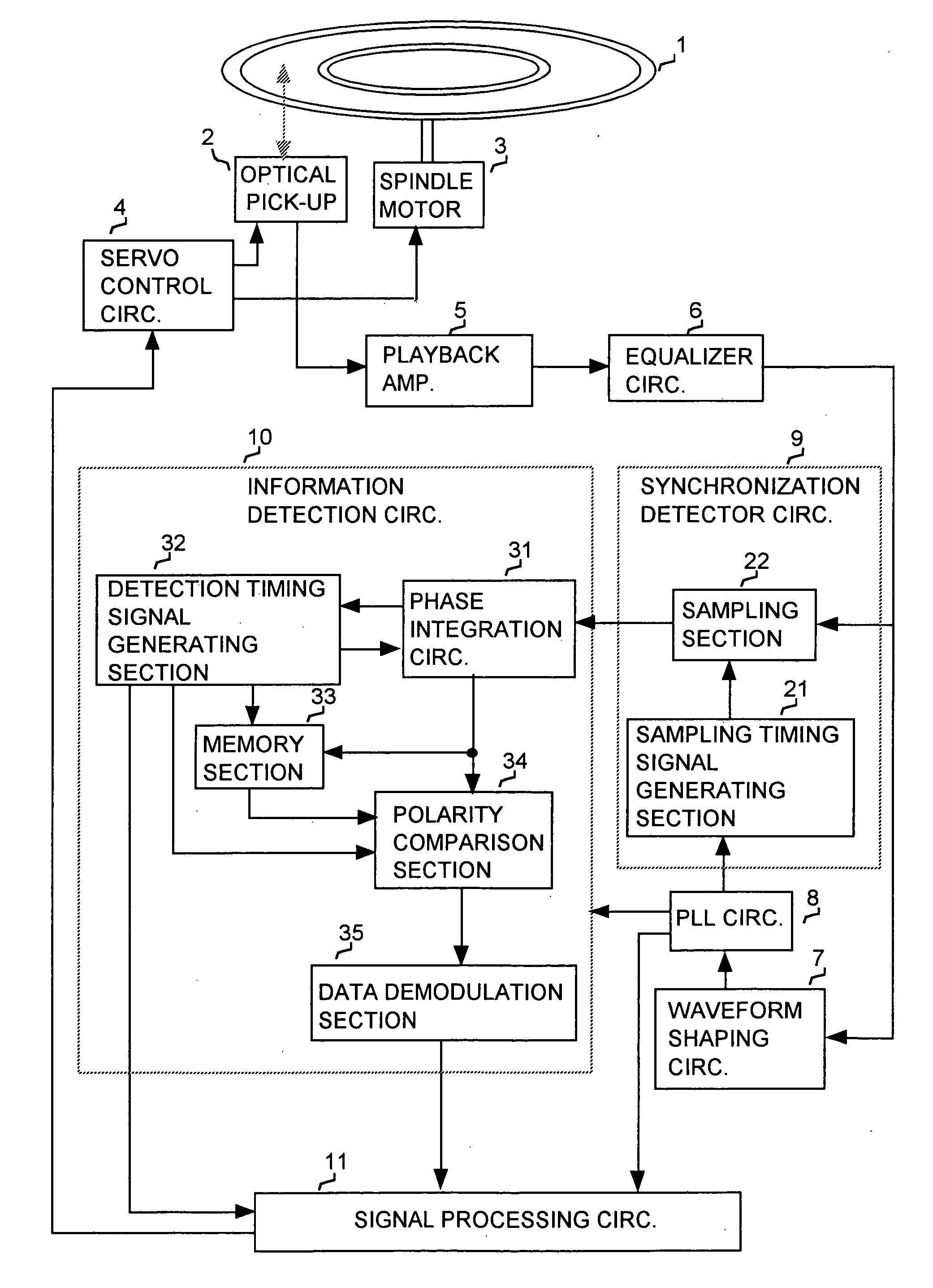
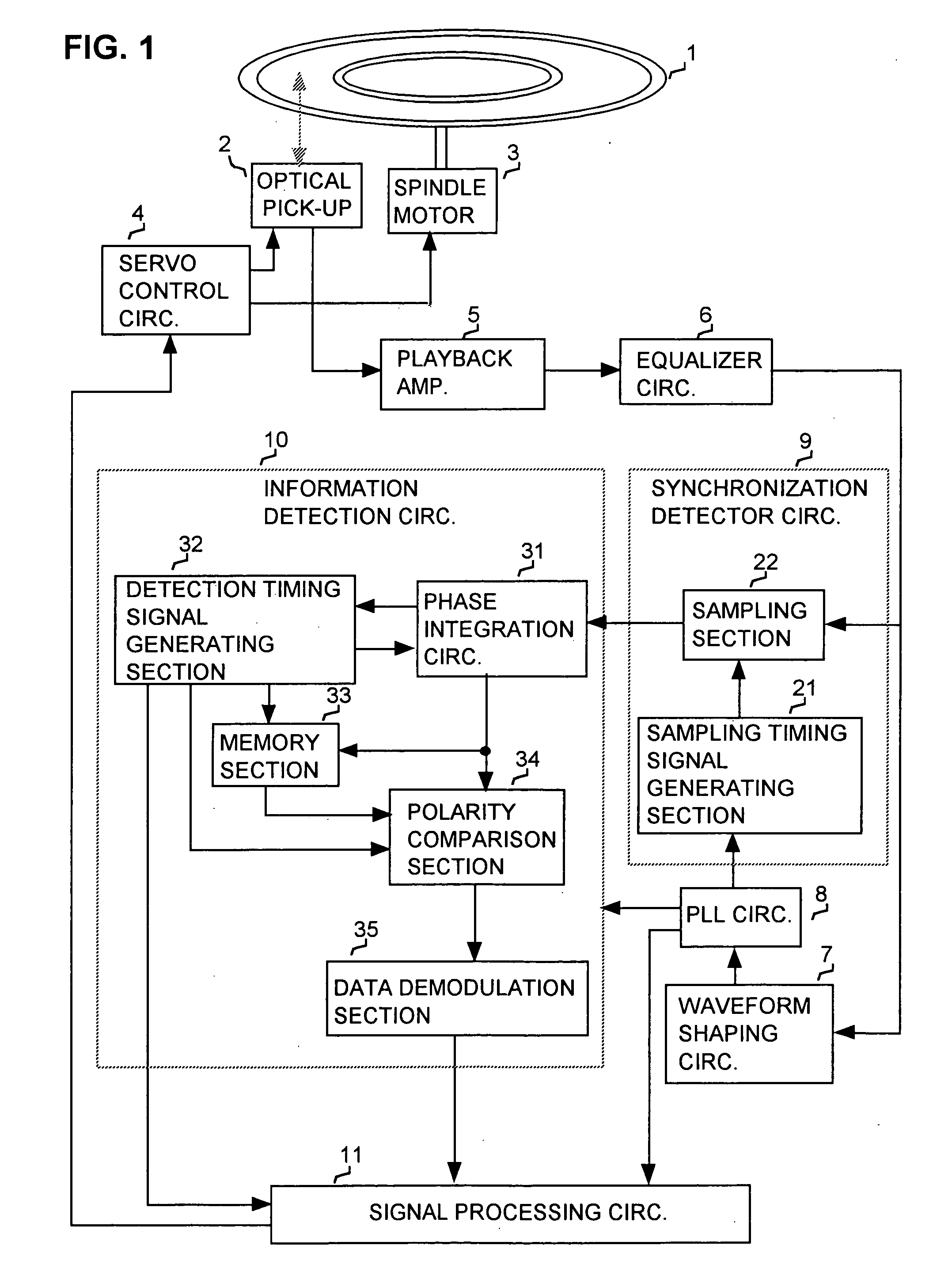
[0054] FIG. 1 is a block diagram of a first embodiment of an optical disk apparatus which incorporates a wobble information detection apparatus. In FIG. 1, an optical disk 1 has track wobble recorded thereon as described above, the wobble being phase-modulated as sections that express a synchronizing pattern (synchronizing information), reference wobble sections that convey reference wobble information, and data wobble sequences which convey information such as track address information. Numeral 2 denotes an optical pick-up, numeral 4 denotes a disk motor for rotating the optical disk 1, numeral 4 denotes a servo control circuit for controlling driving of the optical pick-up 2 and rotation of the spindle motor 3, numeral 5 denotes a playback amplifier for amplifying an optical readout signal (i.e., the playback wobble signal) from the optical pick-up 2, and numeral 6 denotes an equalizer circuit for reducing code errors caused by waveform distortion of the playback wobble signal fro...
second embodiment
[0091] FIG. 4 is a block diagram of a second embodiment of an optical disk apparatus which incorporates a wobble information detection apparatus. As can be understood by comparing FIG. 4 with FIG. 1, the second embodiment differs from the first embodiment of FIG. 1 in that the polarity comparison section 34 is replaced by a calculation section 42 and a level comparison section 43, in the information detection circuit 41. Other components of the second embodiment which correspond to components in the embodiment of FIG. 1 are designated by identical reference numerals to those of FIG. 1, and detailed description of these will be omitted. The following description will be limited to mainly the operation of the calculation section 42 and of the level comparison section 43.
[0092] Firstly, when sample values of the wobble signal are obtained by the synchronous detection circuit 9 and inputted to the information detection circuit 41 after the synchronization pattern has been detected, so t...
PUM
| Property | Measurement | Unit |
|---|---|---|
| specific frequency | aaaaa | aaaaa |
| phase integration | aaaaa | aaaaa |
| phase | aaaaa | aaaaa |
Abstract
Description
Claims
Application Information
 - R&D
- Intellectual Property
- Life Sciences
- Materials
- Tech Scout
- Unparalleled Data Quality
- Higher Quality Content
- 60% Fewer Hallucinations
Browse by: Latest US Patents, China's latest patents, Technical Efficacy Thesaurus, Application Domain, Technology Topic, Popular Technical Reports.
© 2025 PatSnap. All rights reserved.Legal|Privacy policy|Modern Slavery Act Transparency Statement|Sitemap|About US| Contact US: help@patsnap.com


