Mobile prepressurized diaphragm type fluid storage tank

a technology of prepressurized diaphragm and fluid storage tank, which is applied in the direction of liquid handling, lubricant transfer, packaging goods type, etc., can solve the problems of inability to change the type of fluid, initial overhead cost,

Inactive Publication Date: 2004-11-04
AMTROL LICENSING INC
View PDF17 Cites 9 Cited by
  • Summary
  • Abstract
  • Description
  • Claims
  • Application Information

AI Technical Summary

Problems solved by technology

The drawbacks to this system is the initial overhead costs, the lack of versatility to be able to change the type of fluid, a given l

Method used


Image

  • Mobile prepressurized diaphragm type fluid storage tank
  • Mobile prepressurized diaphragm type fluid storage tank
  • Mobile prepressurized diaphragm type fluid storage tank

Examples


Embodiment Construction

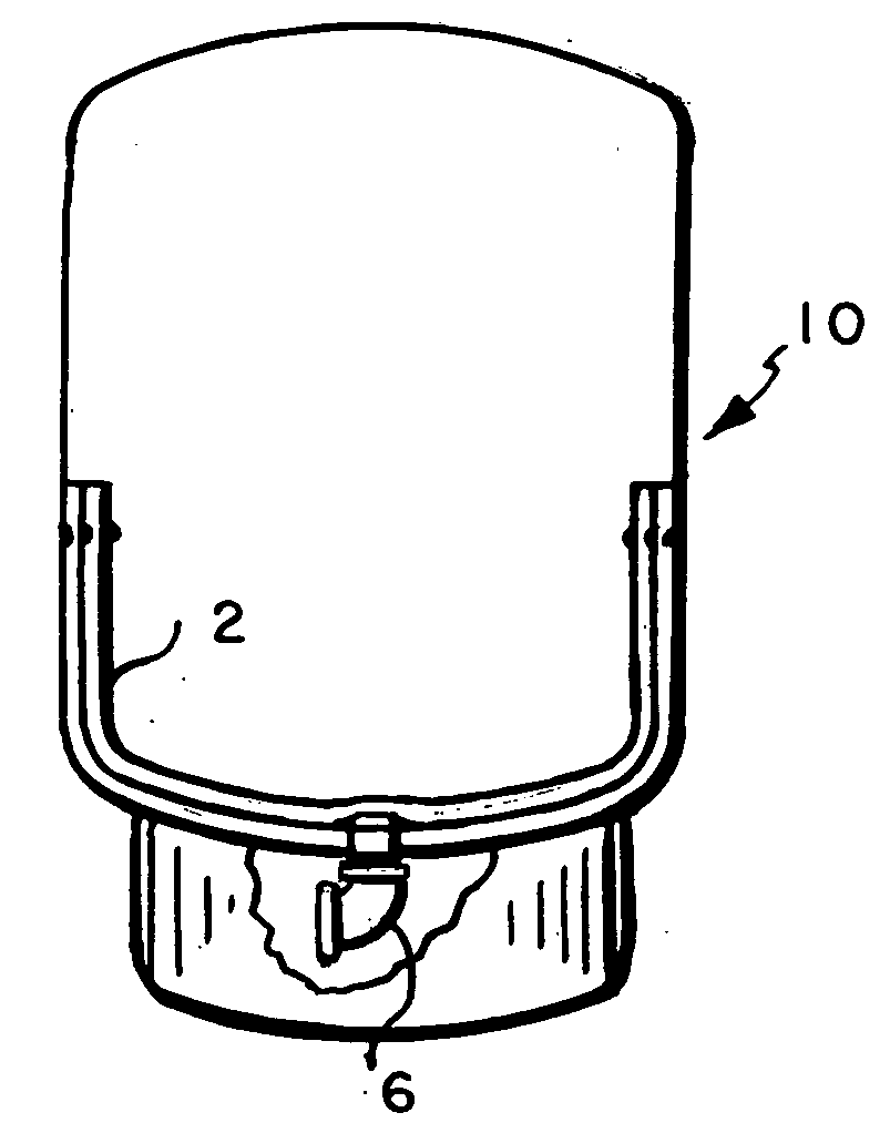
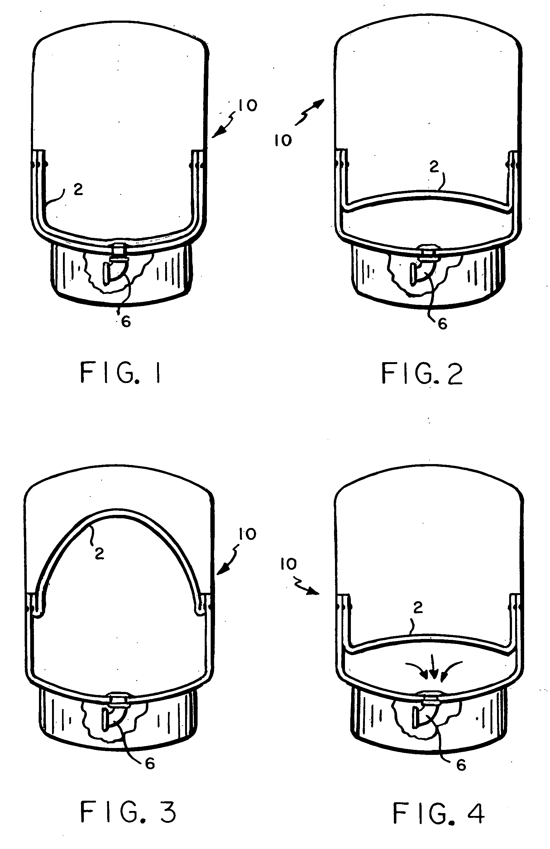
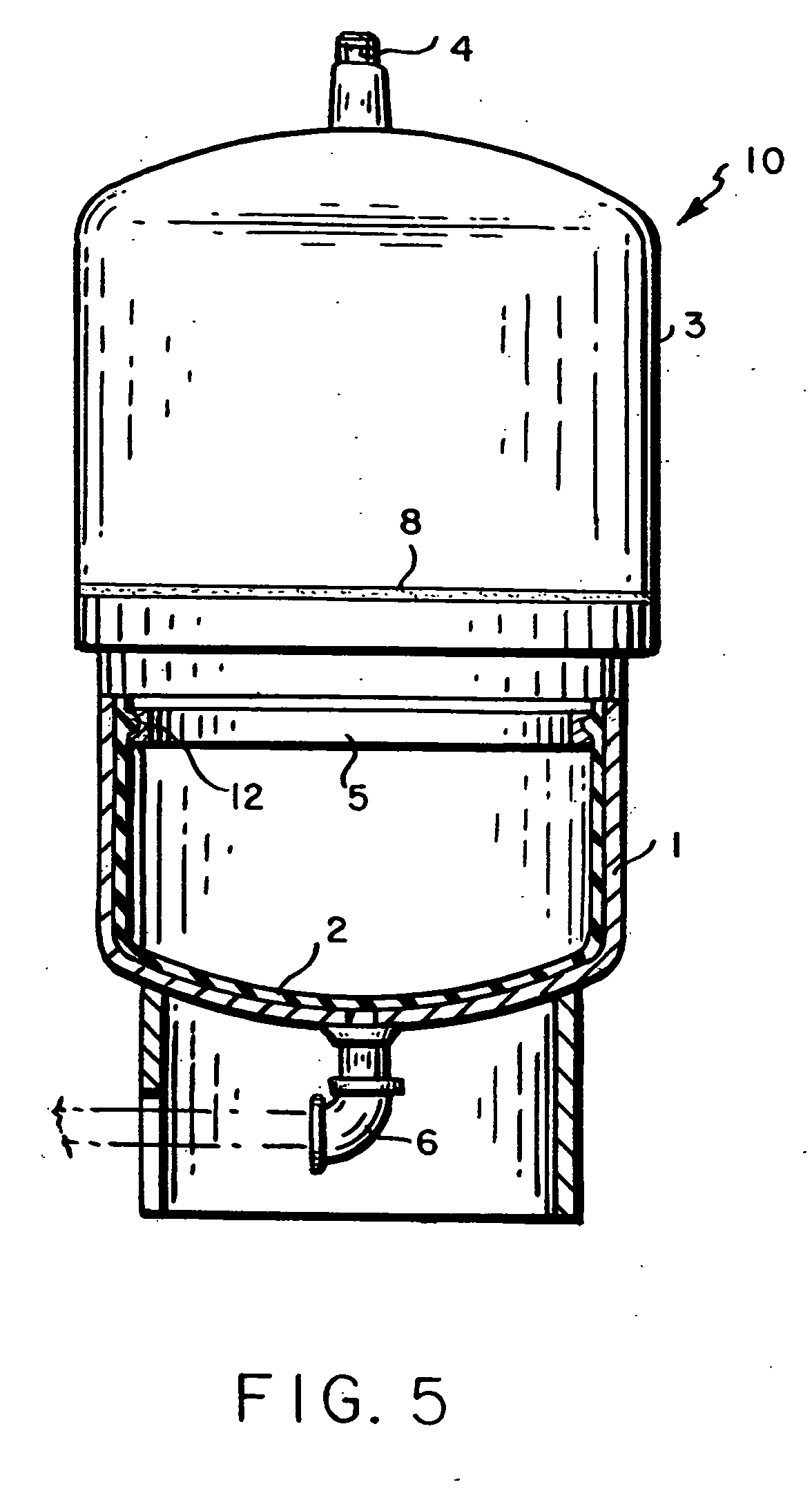
[0032] Referring to the drawings, a mobile prepressurized diaphragm oil storage tank 10 in accord with the present invention comprises a tank attached to a frame adapted for mobility. The frame can have wheels or can be structured for easy pick up by a cart or other transporting means. The storage tank preferably comprises at least two chambers. A lower chamber (1) houses the diaphragm (2). A ring (5) removably attaches the diaphragm to the tank in the lower chamber. Connector (6) permits filling and discharging fluids from the tank.

[0033] The flexible diaphragm (2) is made of an elastomer that is compatible with the fluids that it contacts. It is mechanically locked to the lower chamber (1), preferably with a concave locking ring (5) that mates with a bead (12) in the diaphragm membrane. The diaphragm (2) preferably is molded to conform to the inner shape of the lower chamber (1). The diaphragm bead preferably is an "O" ring type of bead that mates with the ring (5). The wall of th...


PUM

PropertyMeasurementUnit
Pressureaaaaaaaaaa
Displacementaaaaaaaaaa

Abstract

A mobile prepressurized fluid storage tank is disclosed where the compressed air, completely separated from the fluid by a flexible diaphragm, dispenses the fluid under pressure, e.g., into an engine. The prepressurized diaphragm-type fluid storage tank is initially charged with a gas on one side of the diaphragm. A connector on the other end of the tank is connected to the fluid pumping system. Fluid is pumped into the tank until a predetermined pressure is reached and then the fill valve is shut off. A second connection attached to a bottom system connection has a hose. At the end of the hose there is a fluid shut off valve. Dispensing of the fluid takes place through the fluid shut off valve. The prepressurized fluid storage tank is mounted on a frame that contains wheels for mobility.

Description

[0001] This invention relates to a method and apparatus for storing and dispensing oil or other fluids into an engine or other devices.BRIEF DESCRIPTION OF THE PRIOR ART[0002] Changing of automobile engine oil and other fluids varies from the one car garage where each can of oil is opened separately to the multi-bay garages where fixed overhead piping and reel systems are employed. The fixed overhead and reel system eliminates the expense of opening individual cans, the labor involved in opening and disposing of the cans and the added time required to install oil not under pressure. The drawbacks to this system is the initial overhead costs, the lack of versatility to be able to change the type of fluid, a given location being dictated by the fixed piping and hose reel length and the compromise of safety by having overhead hoses under pressure. Oil is pumped from an atmospheric storage tank to the reel hose system, thus, providing the possible presence of water in oil. Thus, the oil...

Claims


Application Information

Patent Timeline
IPC IPC(8): F01M11/04F16N37/00
CPCF01M11/0458F01M2011/0483F16N37/00
Inventor GUILLEMETTE, LARRY T.LANE, JOSEPH A.
Owner AMTROL LICENSING INC
Why Eureka
Try Eureka