Multi-detector detection of optical signals

a detection method and optical signal technology, applied in the direction of optical fiber transmission, dispersion/dispersion elimination, electrical equipment, etc., can solve the problems of imposing practical limits on the length of optical transmission media from which optical signals can be recovered, limiting the effective distance over which optical signals can be transmitted, and exhibiting characteristics of optical fibres

Active Publication Date: 2004-11-04
CIENA
View PDF8 Cites 44 Cited by
  • Summary
  • Abstract
  • Description
  • Claims
  • Application Information

AI Technical Summary

Benefits of technology

[0019] Alternatively, the spectral modes may not be representative of the whole bandwidth of the input optical signal. Advantageously, this could be used, for example, in high dispersion cases to allow a sacrificial mode or modes. That is, some of th information is intentionally discarded within a mode (a sacrificial mode) and the discarded information is inferred from the remaining data which is detected. This may be useful where there are insufficient spectral mode receivers to detect all the spectral modes without incurring a penalty due to the dispersion. However, were the sacrificial mode or modes detected instead of discarded, overall performance could still be improved.

Problems solved by technology

However, known optical media (for example optical fibres) are known to exhibit characteristics which limit the effective distance over which optical signals can be transmitted without requiring detection and regeneration in order to avoid irretrievable corruption of the modulated data.
Both of these effects effectively impose practical limits on the length of optical transmission media from which the optical signals can be recovered using known technology and at reasonable cost without suffering intolerable loss of data (whether through lack of reliability in the data recovered, or through total loss of the signal).
The optical receiving and re-transmission apparatus required at such intermediate points may be complex, costly, and bulky and require ongoing expense arising from powering costs and maintenance costs.
The overall cost of this equipment is ultimately borne by the end-customers making use of such communications networks.
However, th degrading effects of dispersion in the transmission medium which most affect coherent receivers arise as a result of the width of the frequency band rather than the individual frequencies themselves, and so this offset to lower frequencies, whilst retaining the information content of the signal, does not materially mitigate the effects of dispersion since the lower-frequency signal still requires at least the same width of band as the originally transmitted signal.
The phase distortion damage is done during transmission, all coherent mixing down does, is to frequency shift that distorted information.
Known direct detection transmission systems are also limited by optical dispersion.

Method used


Image

  • Multi-detector detection of optical signals
  • Multi-detector detection of optical signals
  • Multi-detector detection of optical signals

Examples


Embodiment Construction

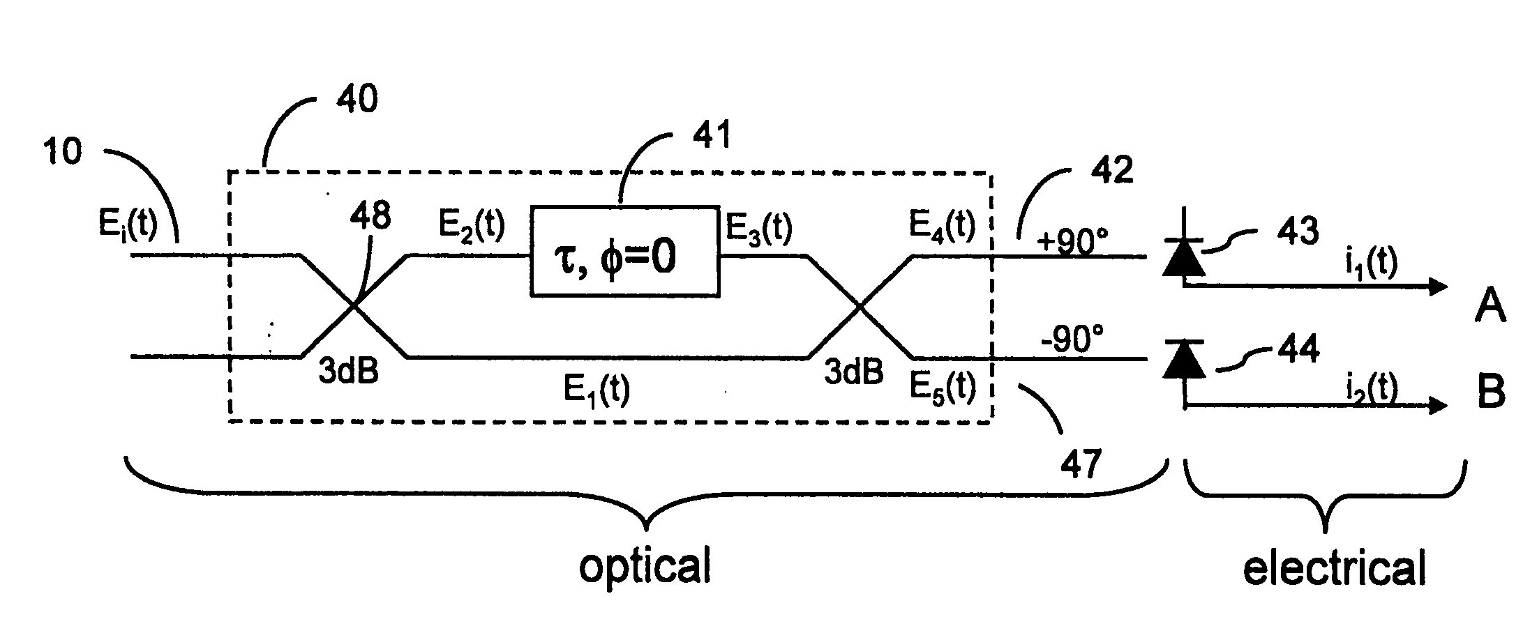
[0049] In conventional direct detection systems utilising only a single photo-detector to detect the received optical signal, high levels of dispersion cannot be compensated electronically after photo-detection since some of the phase information is lost in the photo-detection process. Specifically, because optical dispersion causes a phase shift between upper and lower modulation sidebands of the received signal, the upper and lower modulation sidebands do not sum coherently. As a result, Amplitude Modulation (AM) of the transmitted signal becomes converted to Phase Modulation (PM) of the signal and vice versa.

[0050] The term `detecting` or `photo-detecting` is used herein to refer to the process of converting an optical signal from the optical to the electrical domain.

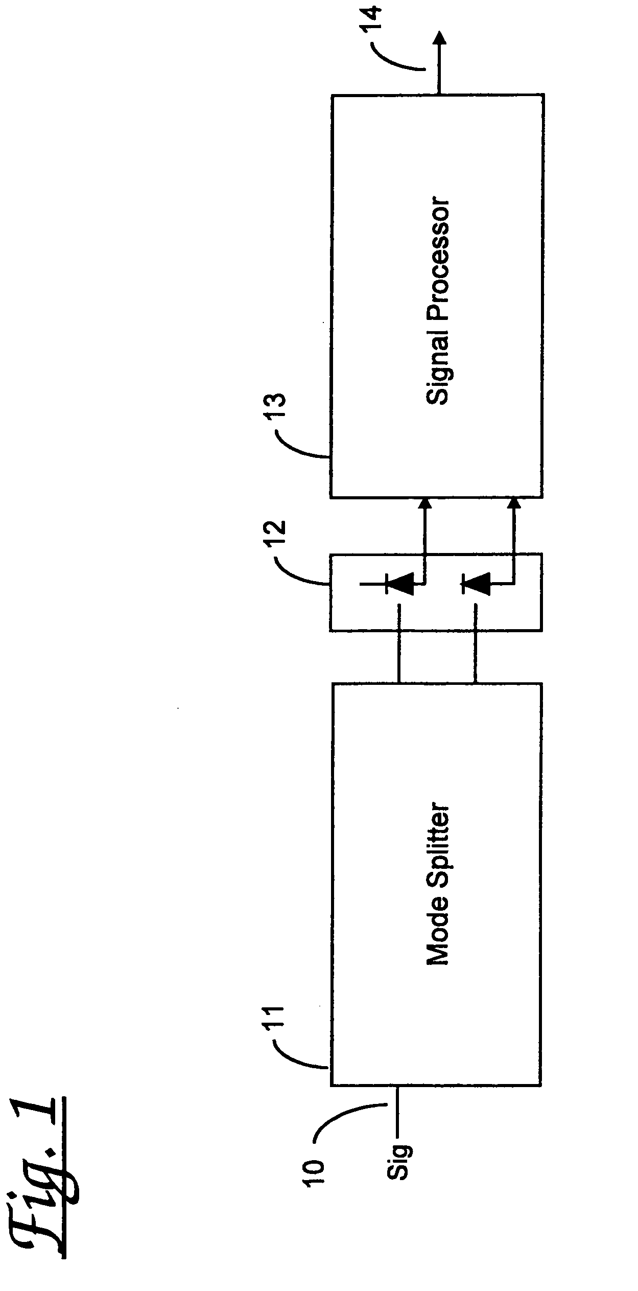
[0051] Referring now to FIG. 1 there is shown a receiver arrangement according to the invention. The receiver arrangement comprises a mode splitter 11 arranged to receive an input optical signal 10 and to produce mul...


PUM


Abstract

Use in an optical communications system of multiple detectors to separately detect respective multiple spectral modes of a received optical signal. The invention also provides for corresponding multi-channel, dispersion-tolerant optical receivers. Embodiments are presented both for direct detection and for coherent detection of optical signals.

Description

[0001] The present invention relates to methods and apparatus for multi-detector detection of optical signals and systems incorporating the same. In particular, coherent detection and direct detection of optical signals of the kind employed in optical communications networks.BACKGROUND TO THE INVENTION[0002] It is known to use optical communications media to carry optically modulated data over great distances in communications networks. However, known optical media (for example optical fibres) are known to exhibit characteristics which limit the effective distance over which optical signals can be transmitted without requiring detection and regeneration in order to avoid irretrievable corruption of the modulated data. Such characteristics include both chromatic dispersion effects and polarisation mode dispersion (PMD) effects. Both of these effects effectively impose practical limits on the length of optical transmission media from which the optical signals can be recovered using kn...

Claims


Application Information

Patent Timeline
Patent Type & Authority Applications(United States)
IPC IPC(8): H04B10/06H04B10/148H04B10/158H04B10/18
CPCH04B10/2513H04B10/60H04B10/697
Inventor EPWORTH, RICHARDANSLOW, PETERFLUDGER, CHRISTOPHER R.
Owner CIENA
Why Eureka
Try Eureka