Magnetic head assembly and magnetic tape servo signal writer

a servo signal and magnetic tape technology, applied in the direction of maintaining the alignment of the head carrier, manufacturing head surface, instruments, etc., can solve the problems of tape bias mechanism, tape edge being pushed against the tape guide, damage, etc., to prevent buckling, strong rigidity, and extreme rigidity against the lateral force

Inactive Publication Date: 2004-11-18
FUJIFILM HLDG CORP +1
View PDF10 Cites 15 Cited by
  • Summary
  • Abstract
  • Description
  • Claims
  • Application Information

AI Technical Summary

Benefits of technology

[0012] In this configuration of the guide blocks adjacent to the servo write head, the passing tape is pushed to contact onto two edges of the servo write head. These two edges make a rectangular shape frame of the passing tape. One of the edges of the servo write head and the opposite edge of the guide block to the servo write head make another rectangular frame of the passing tape. The passing tape is kept in a tension along the sliding direction therefore the tape has rigidity in the right angle to the tension force. Especially, the effect of the rigidity provided in such rectangular frame shape turns into a flexural rigidity against the lateral force against the tape passing direction as given by E.times.I. E is a Young's modulus and I is the secondary section moment which is given by b.times.h.sup.3 / 12 where b is the thickness of the tape and h the width of the magnetic tape. According to the cubic relation to the tape width, the rigidity against the lateral force can be extremely large even for the thin tape base and small Yong's modulus of the tape base. The edges work to hold a beam shape in three dimensional view (as well as the rectangular shape in planer dimensional view) so that such flexible magnetic tapes has strong rigidity against the lateral force or lateral vibration against the tape passing direction in cooperation with the tension that stretches the magnetic tape to maintain the beam shape. The tension to stretch the magnetic tape works to prevent buckling due to the lateral force onto the magnetic tape as well. The tension is generated by the winding force of the tape reel.
[0013] For the case when the servo signal head is equipped with two guide blocks, then another flexural rigidity is added to the flexural rigidity generated by an edge of a guide block and an edge of the servo signal head. Therefore the configuration with two guide blocks serves to further stabilize the passing tape.
[0014] The lap angle .theta.1, that is an angle of attack of the tape against the sliding surface of the servo write head, is preferred to be 1.0 to 6.0 degrees. Because the angle in this range allows the tape sliding on the surface of the servo signal recoding head without damages such as scratching or exfoliation of the recording layer of the tape.
[0015] In the present invention, hardness of the guide block is preferred to be more than 1200 Vickers especially at the edge portion which contacts with the passing tape. For this hardness, the abrasion of the edge portion can be prevented.
[0016] A metal alloy as Al.sub.2O.sub.3.TiC (Aluminum Titanium Carbide) or surface-finishing for hardening is preferred to be used for the guide block since the use of such a metal alloy can prevent abrasion of the guide block.
[0017] In the present invention, it is preferred that the lap angle .theta.1, that is an angle of attack of the tape against the surface of the passing tape sliding through the guide block, is preferred to be 0.5 to 2.0 degrees. In this alignment of the guide block, it is possible that the magnetic tapes can run on the servo write head with appropriate contact without the damages added onto the tape.

Problems solved by technology

However, in this existing technology, it is necessary to control the air pressure for the bias mechanism.
The constant air pressure does not guarantee at the stable tape passing on the tape bias mechanism due to the compressiveness and the dynamic vibration of the air flow and the elasticity of the magnetic tape material.
For the case of the poor alignment of the tape passing direction against the guiding mechanism, an edge of the tape is pushed against the tape guide and damaged by the rubbing with the guide, that is, so-called "edge damage".

Method used


Image

  • Magnetic head assembly and magnetic tape servo signal writer
  • Magnetic head assembly and magnetic tape servo signal writer
  • Magnetic head assembly and magnetic tape servo signal writer

Examples


Embodiment Construction

[0021] By referring to the drawings, we will explain the embodiments of the magnetic head assembly and servo writer regarding the present invention.

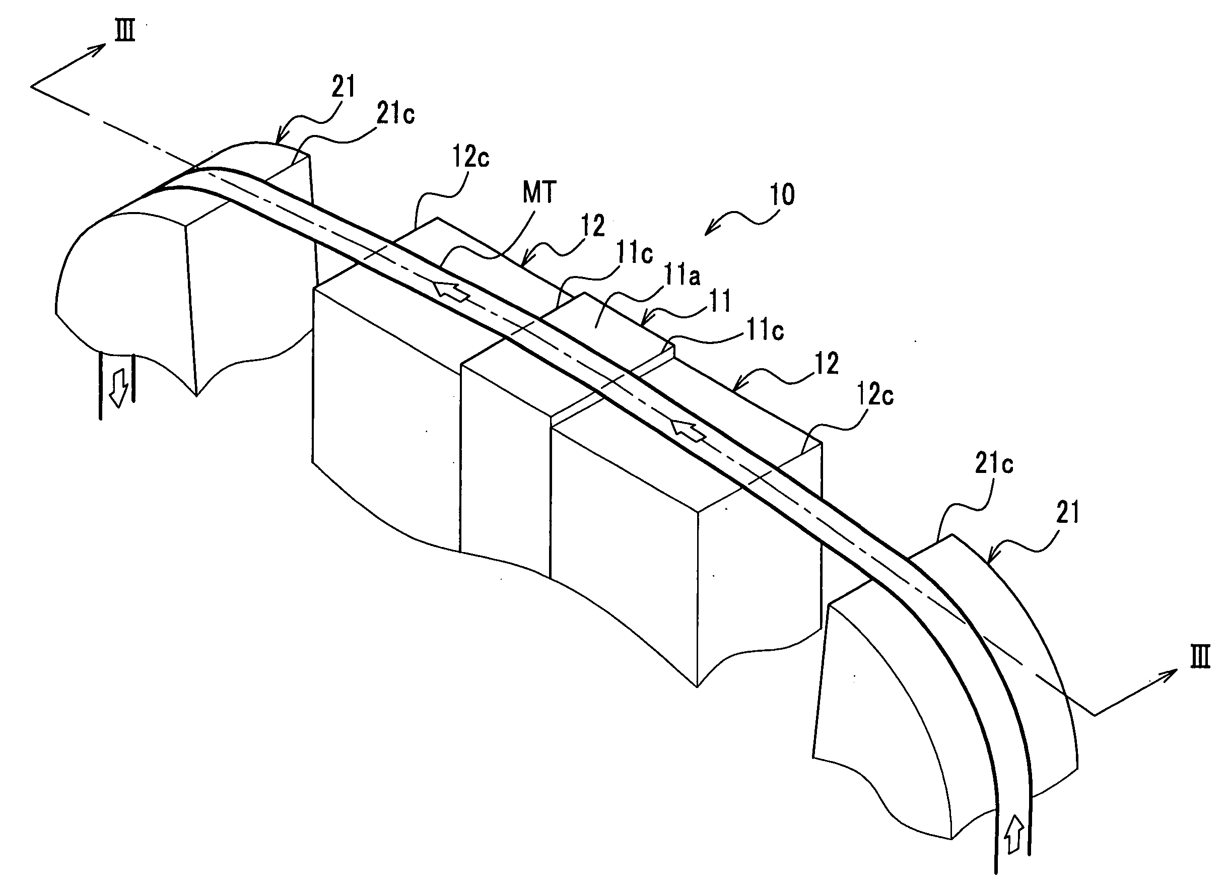
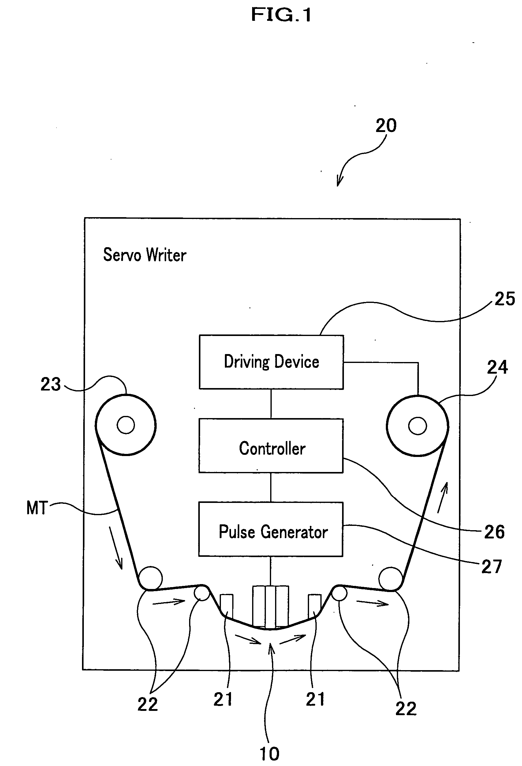
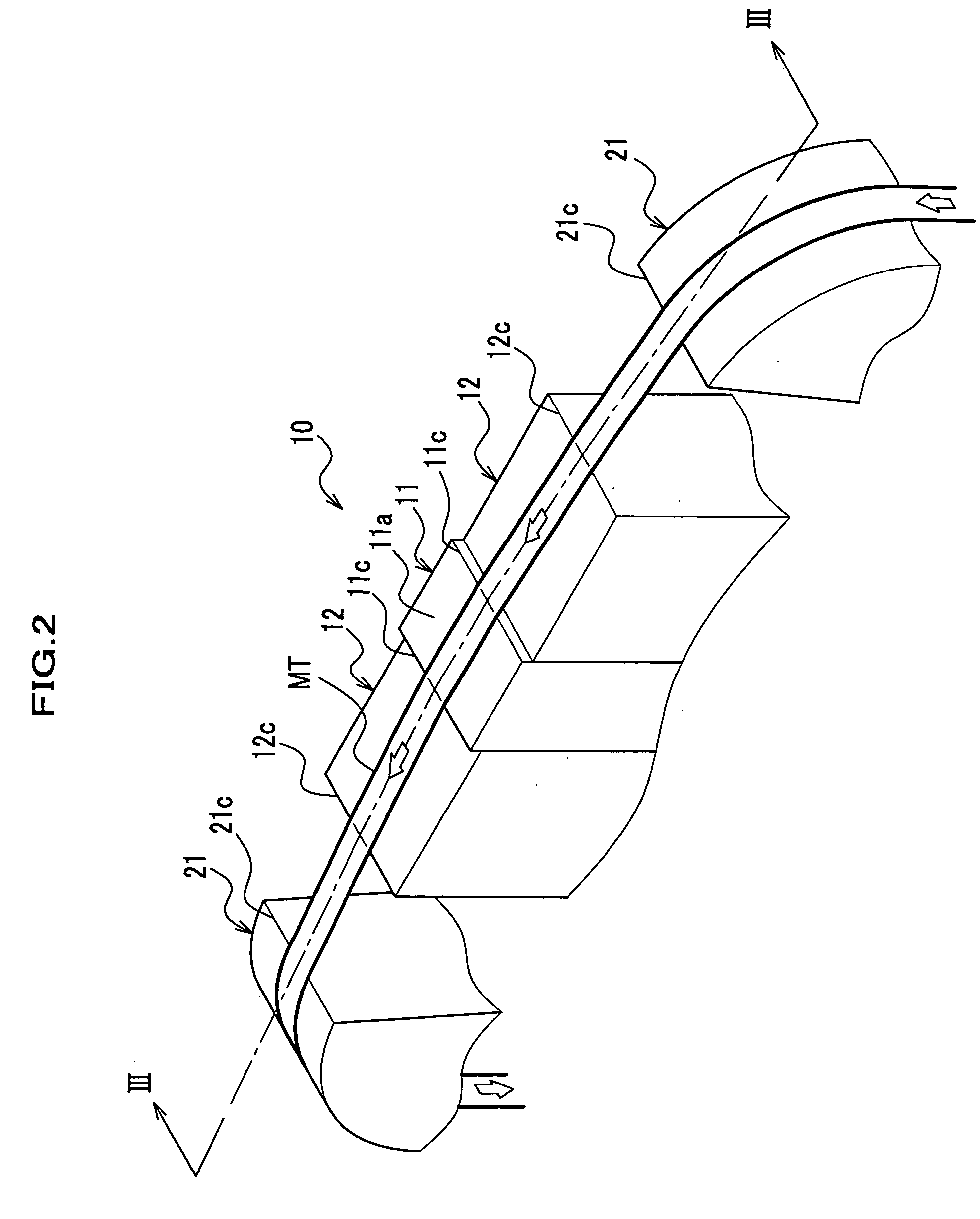
[0022] The FIG. 1 shows an overall conceptual construction of the servo writer in the present embodiment. FIG. 2 shows a perspective view of the magnetic head assembly and FIG. 3 shows the cross sectional view of the magnetic head assembly cut in the line III-III.

[0023] The servo writer 20 is mainly constructed with tape guides 21, guide rollers 22, supply reel 23 and take-up reel 24, driving device 25, a controller 26, a pulse generator 27 and a magnetic head assembly 10.

[0024] The magnetic tape which is not pre-stamped with the servo signals is wound in the supply reel 23. The magnetic tape MT passing out from the supply reel 23 is guided to the magnetic head assembly 10 through the guide roller 22 and tape guide 21. The magnetic tape MT is wound by take-up reel 24 through another set of the tape guide 21 and the guide roller 22. The t...


PUM

PropertyMeasurementUnit
lap angle θ1aaaaaaaaaa

Abstract

A magnetic head assembly to record servo signals, that serves for positing of data recording magnetic heads and data reproducing magnetic heads, on magnetic tapes comprises a servo signal recording head of which sliding surface has a magnetic gap embedded thereon in order to record the servo signals onto a magnetic tape and guide blocks which are set adjacent to at least one of the up-stream position or the down-stream position of a line of magnetic tape passing the servo signal recording head and are slightly set back from said sliding surface of the recording head so that said magnetic tape slides an edge of the servo signal recording head and an edge of the guide block.

Description

[0001] The present invention relates to a magnetic head assembly and the magnetic tape servo signal writer (abbreviated as "servo writer" hereinafter) to which the magnetic head assembly is applied.BACKGROUND OF THE INVENITON[0002] For stamping the servo signals onto the magnetic tapes by using a servo writer, the servo signals are recorded while the magnetic tapes are passing through the magnetic head installed in the servo writer. Since the recorded servo signals are used for the reference tracks to which the operation of the magnetic recording heads or the magnetic reproducing heads are adjusted. Therefore it is quite important to precisely record the servo signals in the position relative to the side edges of the magnetic tapes.[0003] A prior art in a published patent show an example of the servo signal recording technology as shown in the reference 1. This existing technology is to use a combination of a tape guide and a bias mechanism of air pressure so that the tape is slight...

Claims


Application Information

Patent Timeline
Patent Type & Authority Applications(United States)
IPC IPC(8): G11B15/60G11B5/187G11B5/584
CPCG11B5/1871G11B5/584
Inventor NAKAO, TORUIZUMIDA, TAKAHISAHASHIMOTO, AKIHIRO
Owner FUJIFILM HLDG CORP
Why Eureka
Try Eureka