Replaceable soldering tip with sensor recess

a sensor recess and soldering tip technology, applied in the direction of ohmic-resistance heating, manufacturing tools, and solventing apparatus, can solve the problems of oxidization near the gap, poor thermal efficiency, and sleeve 53 to erod

Active Publication Date: 2004-11-25
HAKKO CO LTD
View PDF38 Cites 31 Cited by
  • Summary
  • Abstract
  • Description
  • Claims
  • Application Information

AI Technical Summary

Problems solved by technology

This gap inhibits thermal heat from conducting from the heater 52 to the sleeve 53, resulting in poor thermal efficiency.
After a period of use, oxidization may form near the gap due to high temperature around the gap.
This in turn may cause the sleeve 53 to erode due to oxidization.
The oxidization in the gap further reduces the thermal efficiency of the soldering iron 50.
To compensate for the delay, the conventional soldering irons use expensive control devic

Method used


Image

  • Replaceable soldering tip with sensor recess
  • Replaceable soldering tip with sensor recess
  • Replaceable soldering tip with sensor recess

Examples


Embodiment Construction

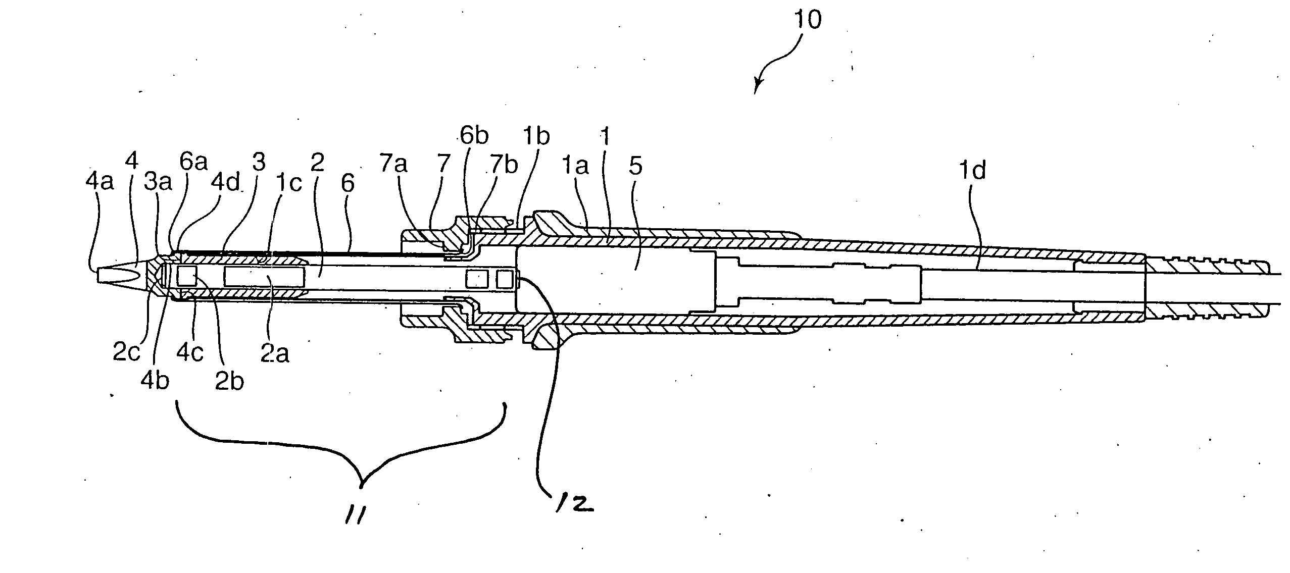
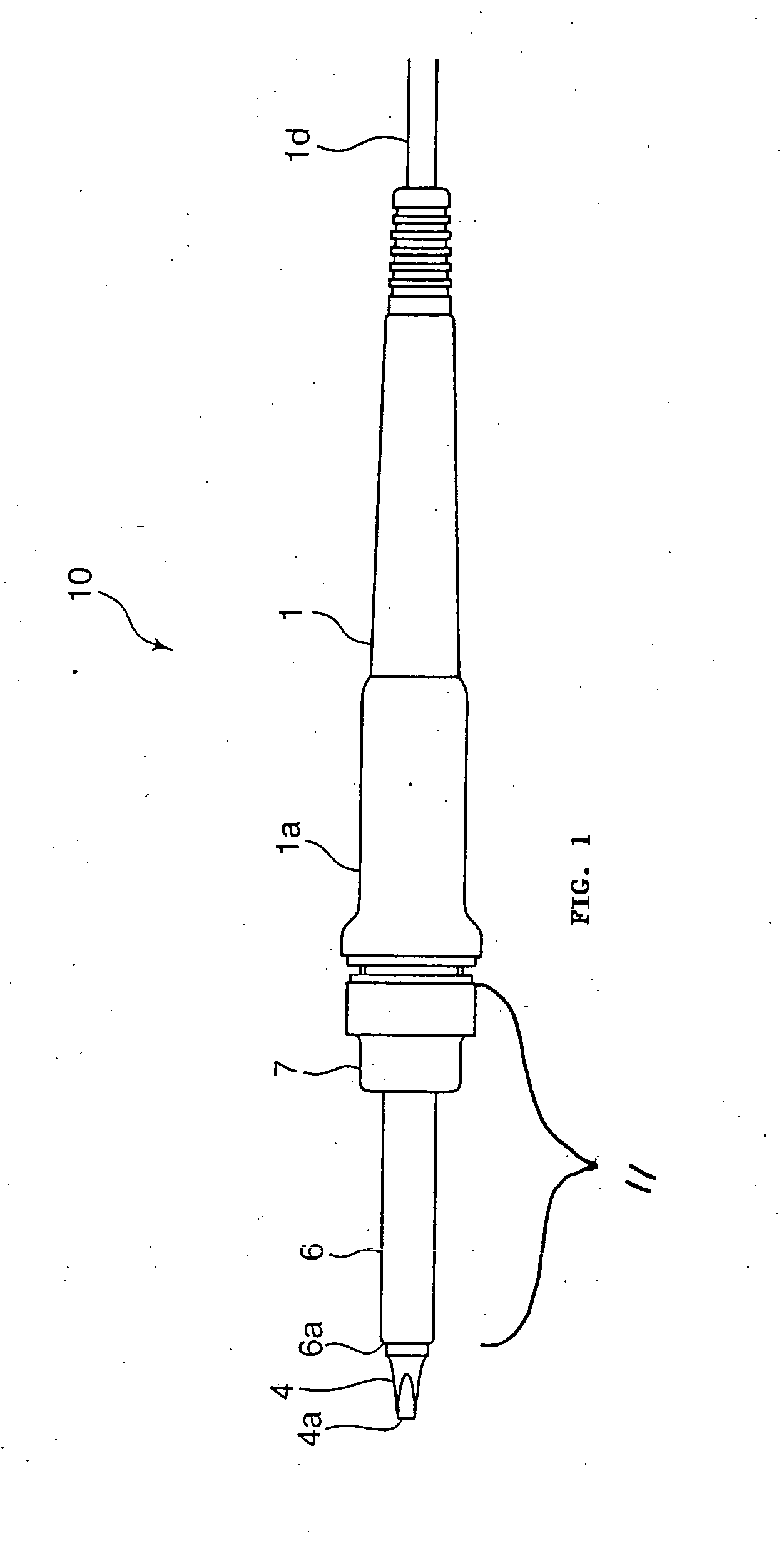
[0051] FIG. 1 illustrates a soldering iron generally at 10 having a heater cartridge assembly 11 and a removable and replaceable tip 4 protruding from the assembly. The tip 4 may be replaced with another tip as the tip wears out or when a different tip is better suited for a particular soldering operation. The soldering iron 10 includes a clamping ring or member 7 that releasably holds the heater cartridge assembly 11 to the casing 1. As further discussed below, the heater cartridge assembly 11 includes a locking tube 6 that retains the tip 4 such that the tip protrudes from the locking tube. To replace the tip 4, the clamping ring 7 may be disengaged from the casing 1 to release the heater cartridge assembly 11 from the casing, and the tip 4 may then be released from the heater cartridge assembly 11 and replaced with another desired tip.

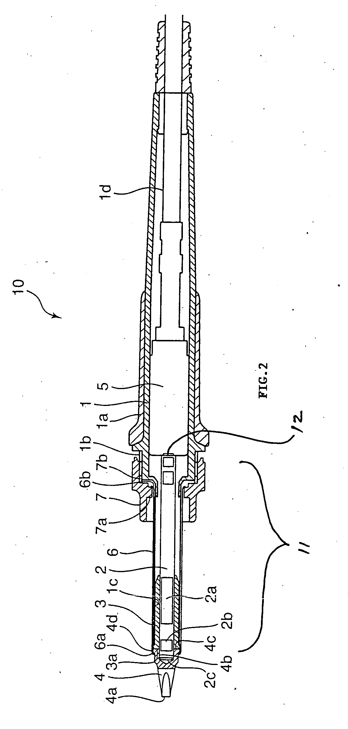
[0052] FIG. 2 is a cross-sectional view of the soldering iron 10, and FIG. 3 is a close up view of the heater cartridge assembly area. The heater c...


PUM

PropertyMeasurementUnit
Lengthaaaaaaaaaa
Lengthaaaaaaaaaa
Lengthaaaaaaaaaa

Abstract

A soldering or a desoldering tool includes a replaceable tip with a recess adapted to receive a portion of a temperature sensor to measure the temperature of the tip. Positioning the temperature sensor within the tip allows the temperature to be quickly measured so that the temperature near the tip may be more accurately monitored and controlled. The temperature sensor may be also integrated with the heater near the tip such that the temperature sensor is between the tip and the heater and near both of them so that the temperature of the tip is substantially that of the temperature of the heater. A sleeve may enclose the temperature sensor and the heater with a portion of the temperature sensor extending out from the foreward end of the sleeve. The replaceable tip may also have a bore adapted to receive a head protruding from the foreward end of the sleeve to couple the tip at a predetermined orientation with respect to the sleeve. The combination of bore and head allows the replaceable tip to be coupled with the sleeve in a consistent manner so that the temperature of the replacement tips can be measured accurately and dependably.

Description

[0001] This application claims priority to Japanese Patent Application No. JP-App-2003-191852, filed Jul. 4, 2003, which is hereby incorporated by reference.[0002] 1. Field of the Invention[0003] This invention relates to a soldering iron or a desoldering iron, and in particular to a soldering (or desoldering) iron capable of accurately measuring the temperature of its tip and of having its tip replaced if needed.[0004] 2. Background of the Invention[0005] FIG. 11 is a cross-sectional view of a conventional soldering iron 50 in a disassembled state. The conventional soldering iron 50 has an insert pipe 51 for coupling a heater 52 to a sleeve 53 which has a protruding tip 54. The heater 52 is removeably inserted into the sleeve 53 so that heat from the heater is conducted to the tip 54. The insert pipe 51 is positioned between the sleeve 53 and the heater 52; when in position a gap is formed between the sleeve 53 and the heater 52. This gap inhibits thermal heat from conducting from ...

Claims


Application Information

Patent Timeline
IPC IPC(8): B23K3/04B23K3/02B23K3/03
CPCB23K3/033B23K3/0353B23K3/0369B23K3/04B23K3/027
Inventor MASAKI, HIROYUKI
Owner HAKKO CO LTD
Why Eureka
Try Eureka