Display device

a display device and display technology, applied in the direction of static indicating devices, instruments, locomotives, etc., can solve the problems of significant time and failure to disclose a specific structur

Inactive Publication Date: 2004-11-25
SANYO ELECTRIC CO LTD
View PDF34 Cites 10 Cited by
  • Summary
  • Abstract
  • Description
  • Claims
  • Application Information

AI Technical Summary

Benefits of technology

[0011] The present invention advantageously provides a structure in which both a voltage signal and a current video signal are used to complete writing of data relatively quickly, and a current-driven pixel circuit is used to achieve precise control of a light emission current.

Problems solved by technology

The '659 Publication, however, fails to disclose a specific structure for a driver for supplying a data current onto the data line.
When a data current is actually supplied to the data line to set the gate voltage of the driver TFT, there is a problem in that a significant time is required for this setting of the gate voltage.

Method used


Image

  • Display device
  • Display device
  • Display device

Examples


Embodiment Construction

[0028] Preferred embodiments of the present invention will now be described referring to the drawings.

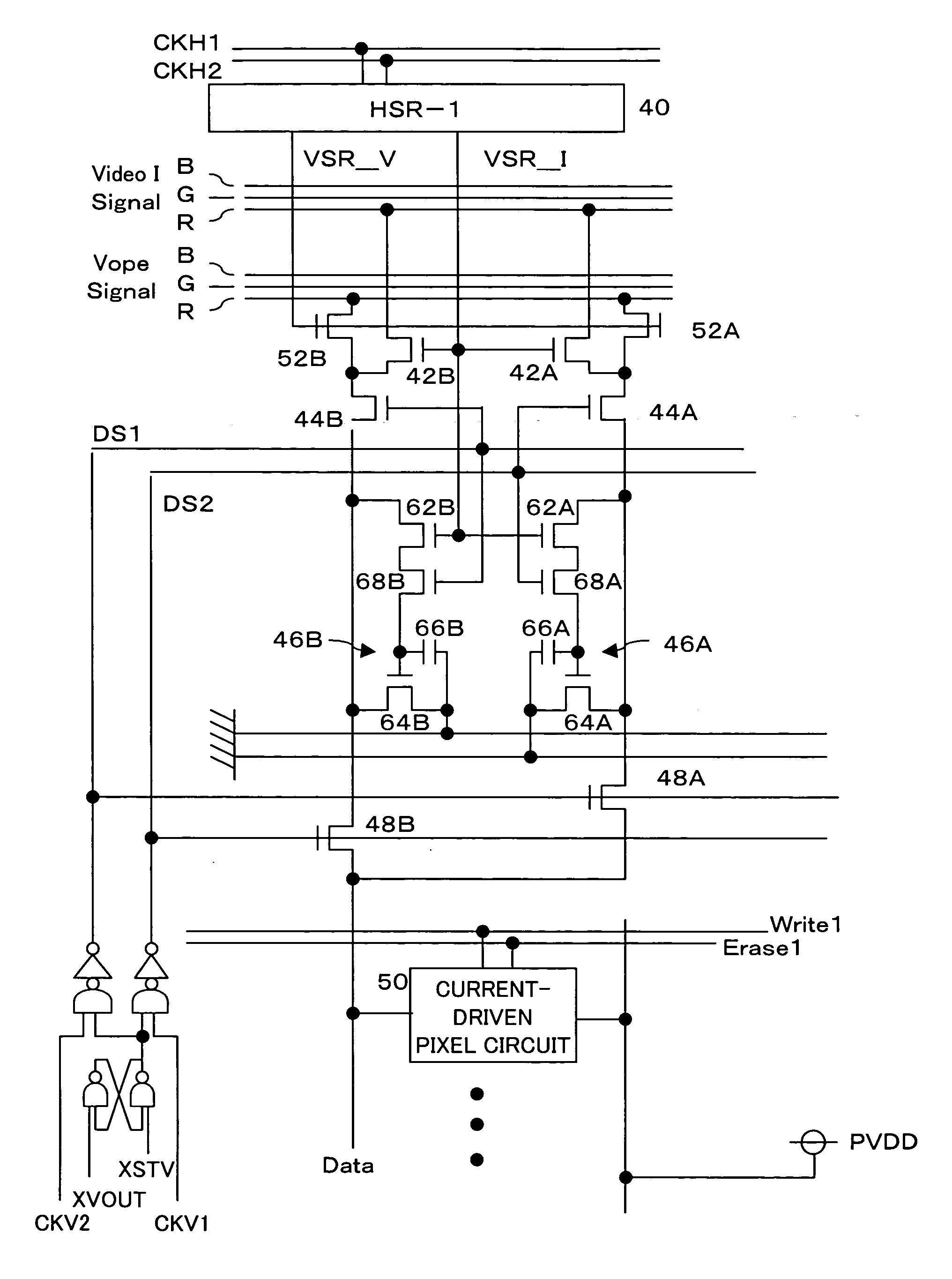
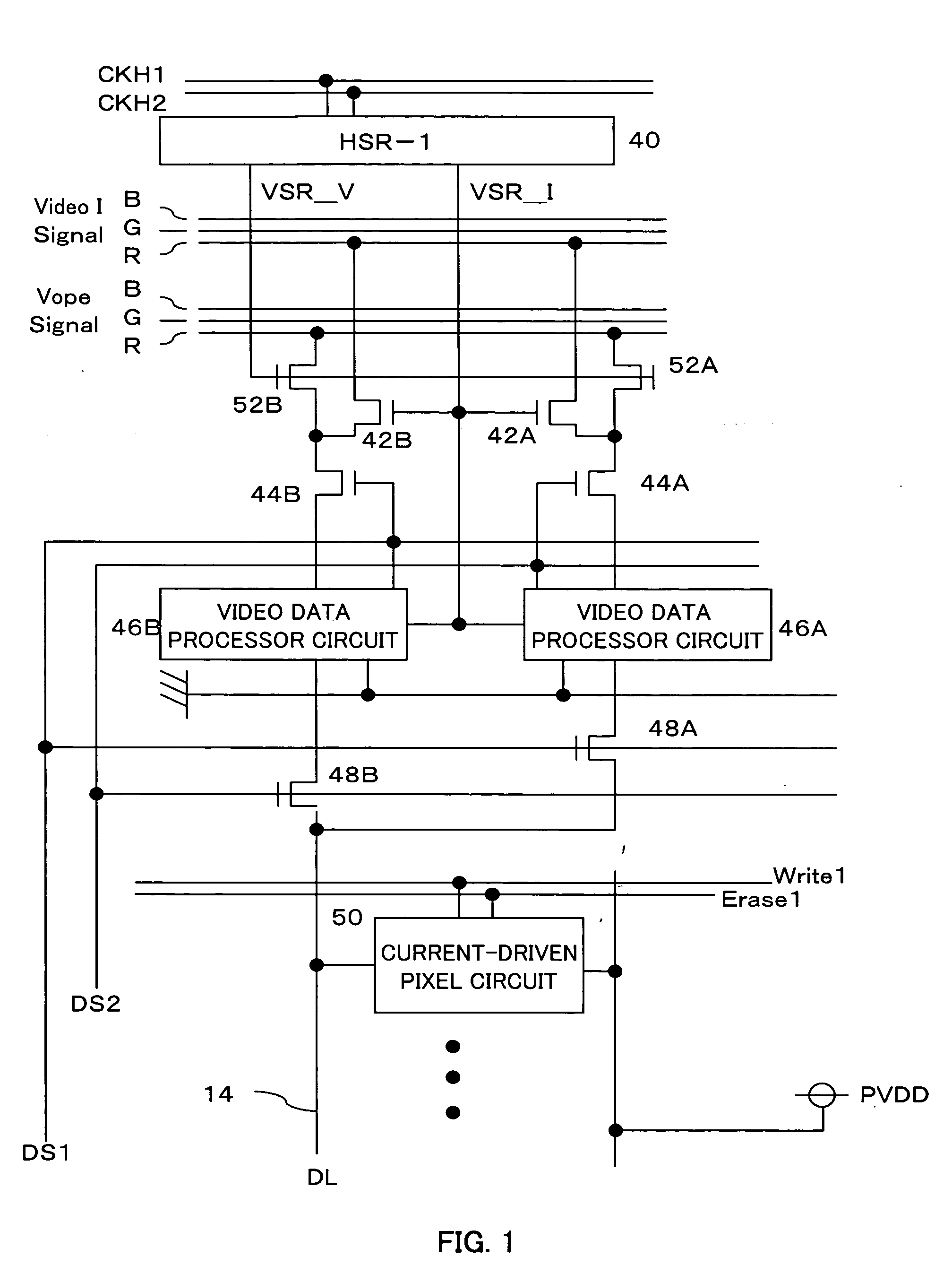
[0029] FIG. 1 is a diagram showing a structure of a first preferred embodiment. A pair of clocks CKH1 and CKH2 are input into a horizontal shift register 40. The clocks CKH1 and CKH2 are signals which repeat H and L levels based on a video signal for each pixel and correspond to a pixel clock in a typical video signal. The clock CKH2 is an inverted signal of the clock CKH1.

[0030] Gates of a pair of n-channel TFTs 42A and 42B are connected to an output VSR_I of the horizontal shift register 40 and gates of a pair of n-channel TFTs 52A and 52B are connected to an output VSR_V of the horizontal shift register 40. Drains of the TFTs 42A and 42B are connected to a line for supplying a current video signal VideoISignal (in the illustrated structure, R signal line) and drains of the TFTs 52A and 52B are connected to a line for supplying an operation point voltage signal VopeSignal (in the ...


PUM


Abstract

An operation point voltage signal and a current video signal are received and stored in a video data processor circuit and a current signal is output onto a data line for a period of one horizontal line. A current-driven pixel circuit can be driven by an operation point voltage signal and a current video signal.

Description

[0001] 1. Field of the Invention[0002] The present invention relates to a display device in which a current video signal is supplied to each of pixels formed in a matrix form, a current corresponding to the current video signal is supplied to an emissive element, and display is achieved.[0003] 2. Description of the Related Art[0004] Because electroluminescence (hereinafter simply referred to as "EL") display devices in which a self-emitting EL element is used as an emissive element in each pixel have advantages such as that the device is thin, self-emitting, and consumes less power, EL display devices have attracted much attention as alternatives to display devices such as liquid crystal display (LCD) and cathode ray tube (CRT) display devices.[0005] In particular, a high resolution display can be achieved by an active matrix EL display device in which a switching element such as a thin film transistor (hereinafter simply referred to as "TFT") for individually controlling an EL elem...

Claims


Application Information

Patent Timeline
Patent Type & Authority Applications(United States)
IPC IPC(8): H01L51/50G09G3/20G09G3/30G09G3/32G09G5/00H05B33/14
CPCG09G3/3283G09G5/02G09G2310/0262G09G2310/0248G09G2310/0251G09G2300/0408B61B13/02B61C11/04B61K7/18
Inventor MATSUMOTO, SHOICHIROOGAWA, MIWA
Owner SANYO ELECTRIC CO LTD
Why Eureka
Try Eureka