Reflective optic system for imaging microplate readers

a microplate reader and reflector technology, applied in the field of fluorescence and luminescence analytical techniques, can solve the problem of reducing the overall assay throughpu

Inactive Publication Date: 2004-11-25
MOLECULAR DEVICES
View PDF18 Cites 32 Cited by
  • Summary
  • Abstract
  • Description
  • Claims
  • Application Information

AI Technical Summary

Problems solved by technology

However, the severely limited field of view of such systems reduces overall assay throughput.

Method used


Image

  • Reflective optic system for imaging microplate readers
  • Reflective optic system for imaging microplate readers
  • Reflective optic system for imaging microplate readers

Examples


Embodiment Construction

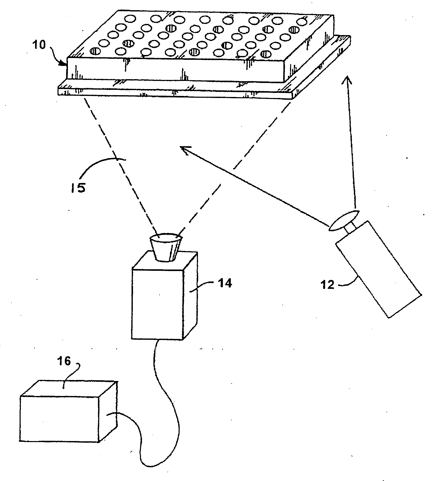
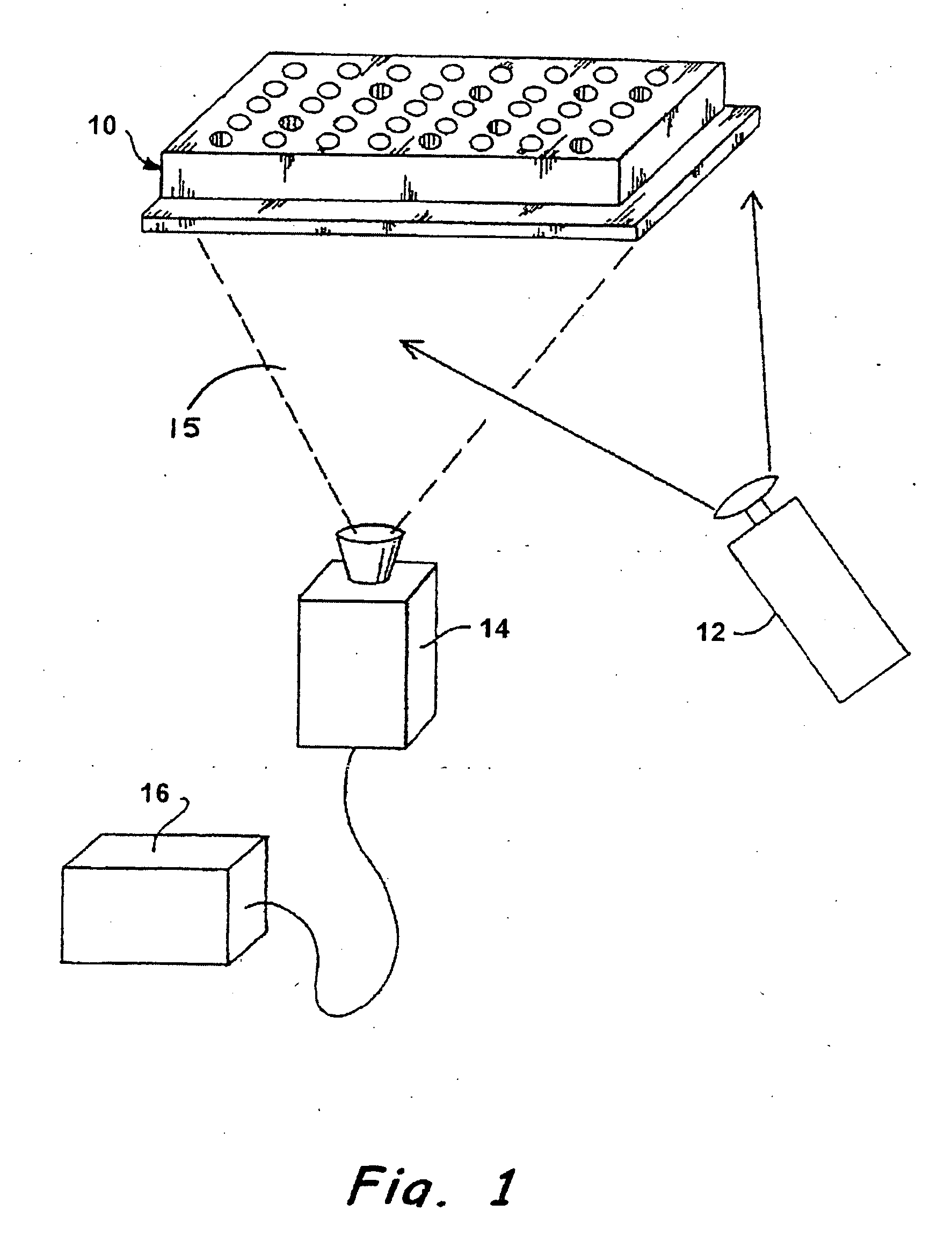
[0015] Typically, optics to image multi-well plates include very large refractive systems, with many lens elements. Plates having up to 1,536 wells, however, present a problem for conventional optics because each well is necessarily smaller than wells of a 384 well plate used in conventional systems, and accordingly samples in the wells produce less total light. In addition, higher optical resolution is required, and must be available over a relatively wide field. A wide field of View is desirable for high throughput, as it permits a 1,536 well plate to be imaged simultaneously with high efficiency.

[0016] Illuminating multi-well plates with lasers can enable simultaneous imaging due to the intensity of lasers. Laser illumination, however, can be troublesome because the high-powered lasers used may require three-phase electrical power and their own water-cooling systems. Further, laser illumination is not color versatile--that is, it lacks the ability to excite samples at a wide vari...


PUM


Abstract

A reflective light imaging system for use in high-throughput screening of samples disposed in multiple-well plates. The system can include a set of mirrors and lenses. The first mirror has a central aperture through which light from the object passes. The first mirror has a concave reflective surface that faces the image plane. The next element is a second mirror with a convex reflective surface. The system can include an aberration corrective system positioned between the second mirror and the image plane, and an optical sensor near the image plane. Light from an object passes through the central aperture of the first mirror and is reflected off the convex surface of the second mirror. The light then strikes the reflective surface of the first mirror. The light from the first mirror is then collected by the aberration correction system and transmitted toward the image plane.

Description

[0001] This application claims benefit to the filing date of Provisional Patent Application Serial No. 60 / 434,291, filed on Dec. 17, 2002, the contents of which are incorporated herein by reference.[0002] 1. Field of the Invention[0003] This invention relates generally to fluorescence and luminescence analytical techniques, and, more specifically, to an optical system that permits high-throughput, simultaneous measuring of the fluorescence or luminescence of a plurality of samples disposed in a multi-well plate.[0004] 2. Background of the Invention[0005] Fluorescence and luminescence measurements are employed in a variety of analyses, and in such-techniques, illumination of a first wavelength absorbed by a sample induces the sample to emit light of a second wavelength. The wavelength and / or intensity of the secondary emission may be correlated with composition, concentration, physical environment and similar parameters. In one particular class of fluorescence analyses, cells of vari...

Claims


Application Information

Patent Timeline
Patent Type & Authority Applications(United States)
IPC IPC(8): G02B17/06G02B27/00
CPCG01N21/6428G01N21/6452G02B17/061G02B27/0025
Inventor JIANG, WUFRENCH, TODD E.STUMBO, DAVID P.
Owner MOLECULAR DEVICES
Why Eureka
Try Eureka