

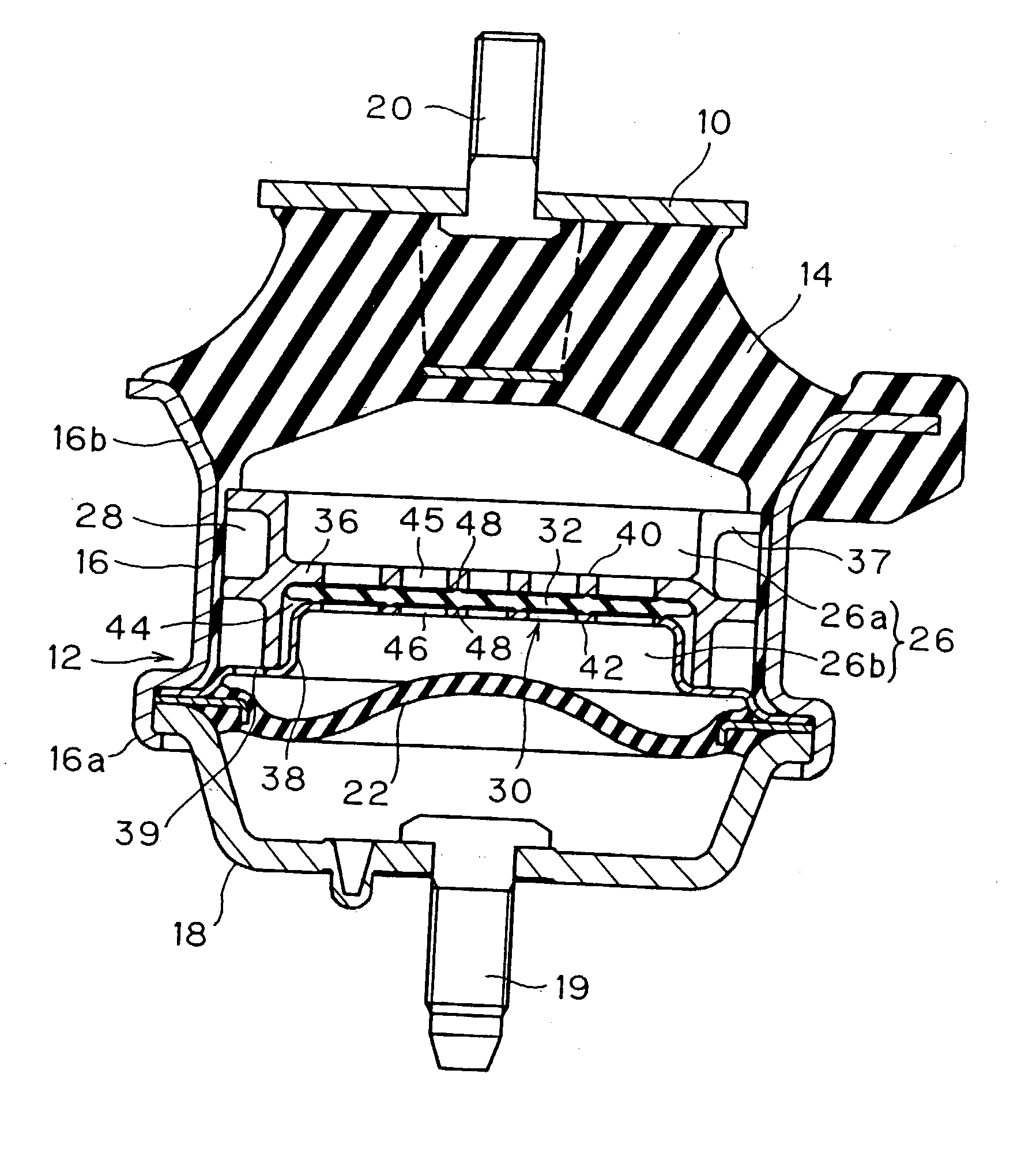
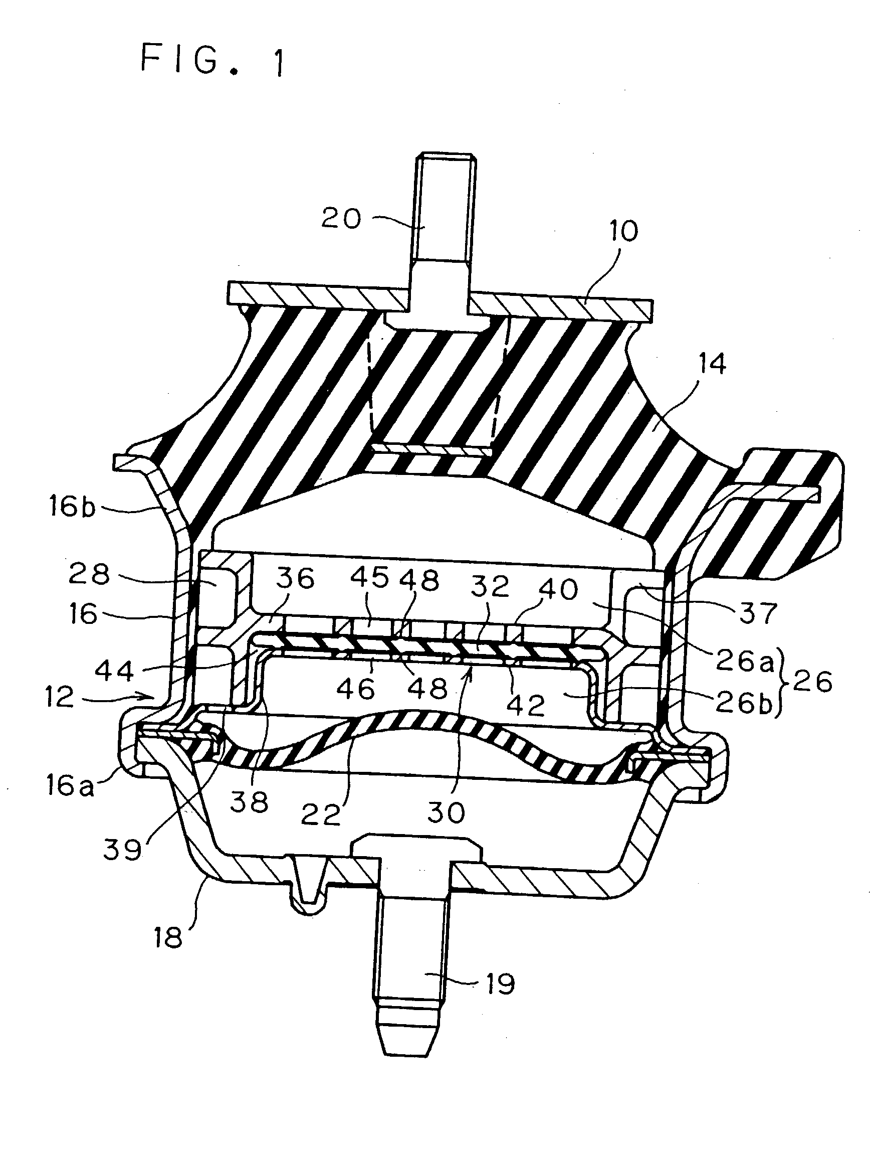
Fluid-sealed anti-vibration device
a technology of anti-vibration and seal, which is applied in the direction of shock absorbers, machine supports, transportation and packaging, etc., can solve the problems of difficult to exhibit higher performance, difficult to prevent the generation of impinging sound and noise not necessarily sufficiently, and the peripheral part of the elastic membrane to flap
- Summary
- Abstract
- Description
- Claims
- Application Information
AI Technical Summary
Benefits of technology
Problems solved by technology
Method used
Image

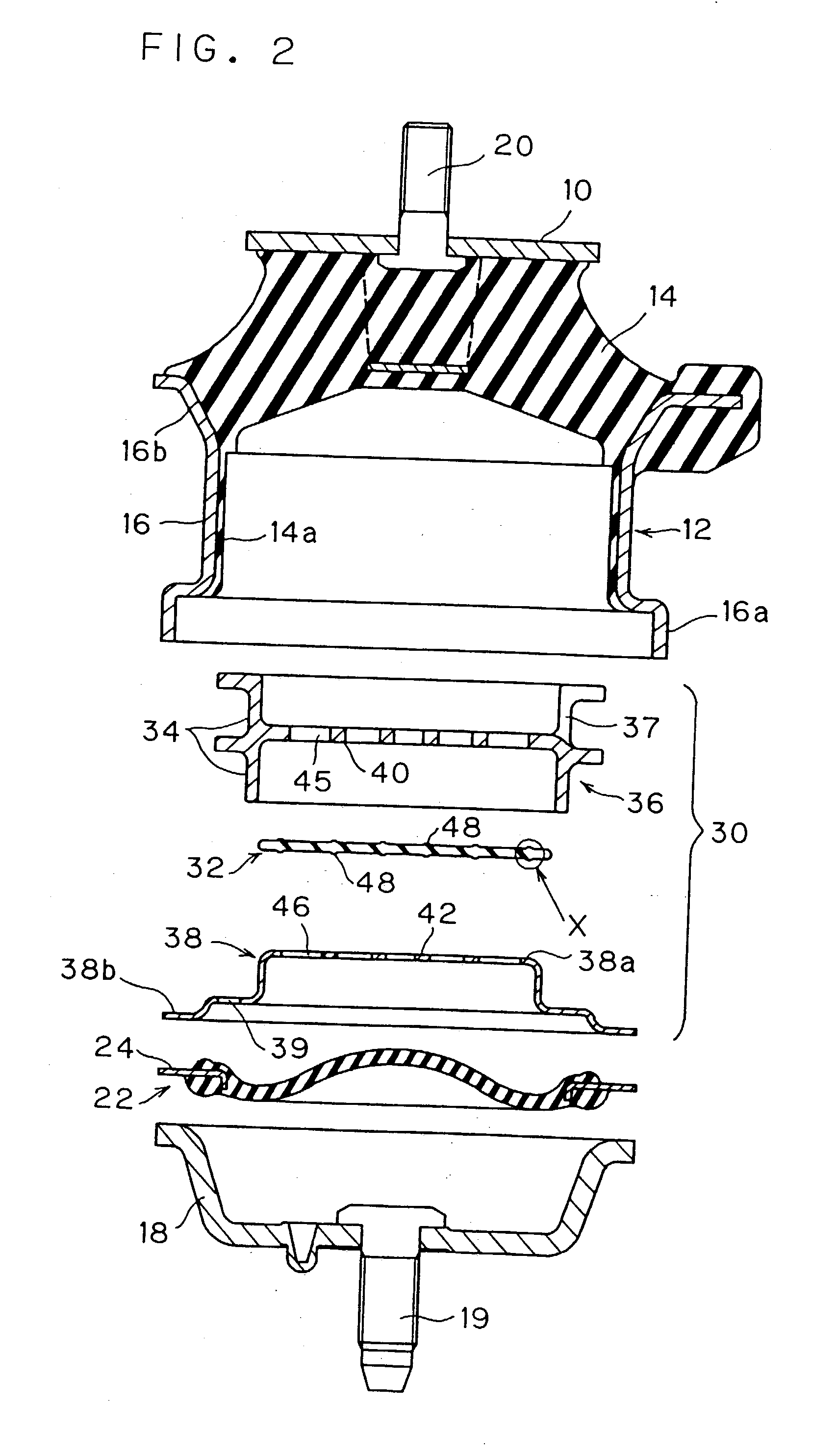
Examples
second example
[0056] The second example is, as shown in FIGS. 5A and 5B, such an example that a positioning construction of the rubber membrane 32 in the revolution direction is added to the first example above. That is, in this second example, the rubber membrane 32 is provided with an ellipsoidal lug (projection) 50 for positioning that project at the lower member 38 side. The lug 50 is situated in the center of the rubber membrane 32. The lower member 38 is provided, in the center of the central shelf part 38a, with a recess 52 for positioning and receiving the lug 50 therein. The recess 52 is of a complementary elongate hole conforming to the contoured form of the lug 50.
[0057] According to this second example, in assembling the rubber membrane 32 onto the lower member 38, the rubber membrane 32 is rested on the grid 42 of the lower member 38 while the lug 50 of the rubber membrane 38 is fitted in the recess 52 of the lower member, whereby it is possible to ride securely the radial projecting...
third example
[0059] FIGS. 6 to 9 indicate a third example of this invention. The third example is similar to the first example except for the construction of the partition member comparting the fluid-sealed chamber 26. The similar elements designated by like reference numerals in the first example have the same construction, and their detailed explanation will be hereinafter omitted unless otherwise stated.
[0060] In the third example, the partition member 100 comparting the fluid-sealed chamber 26 is made up of a disk-like rubber membrane 102 as a valve member partitioning the first chamber 26a and the second chamber 26b, an upper member (a first member) 106 having a groove 104 for forming the orifice channel 28 at its outer periphery, and a lower member (second member) 108 pressing the outer peripheral portion of the upper member 106 toward the vibration-insulating base 14 side.
[0061] The upper member 106 is fashioned of a molding body made of metal or resin, and includes a grid (the first grid...
fourth example
[0070] FIGS. 10 to 12 indicate a fourth example of this invention. The fourth example is different from the first example in construction of the partition member dividing the fluid-sealed chamber 26. The fourth example will be hereinafter described, but the description on similar elements designated by like reference numerals to the first example will be omitted unless otherwise stated, since these are regarded as being of the same construction.
[0071] In the fourth example, a partition 200 comparting the fluid-sealed chamber 26 comprises a disk-like rubber membrane 202 as a valve member partitioning the first chamber 26a and the second chamber 26b, an upper member (the first member) 204 disposed at the vibration-insulating base 14 side relative to the rubber membrane 202, and a lower member (the second member) 206 disposed at the diaphragm 22 side relative to the rubber membrane 202.
[0072] The upper member 204 is a molding product of resin (e.g. polyphthalamide), and includes, as il...
PUM
 Abstract
Description
Claims
Application Information