Alarm condition distributed fiber optic sensor with storage transmission-reflection analyzer

a technology of transmission-reflection analyzer and fiber optic sensor, which is applied in the direction of fluid tightness measurement, force measurement by measuring optical property variation, instruments, etc., can solve the problems of inability to reverse the approach, inaccurate and limited fiber optic sensors, and optimal prior art fiber optic sensors

Inactive Publication Date: 2004-12-02
CENTRO DE INVESTIGACION CIENTIFICA Y DE EDUCACION SUPERIOR DE ENSENADA +1
View PDF4 Cites 29 Cited by
  • Summary
  • Abstract
  • Description
  • Claims
  • Application Information

AI Technical Summary

Problems solved by technology

This type of prior art fiber optic sensor, however, is not optimal.
The fiber optic sensor is inaccurate and limited in the distance over which it may be used.
This approach, however, clearly is not reversible since it depends upon destruction of the shear pins upon contact with the hydrocarbon.
In general, prior art detectors have been unduly complicated, and thus, both expensive and prone to erroneous signals.
The authors of these inventions do not teach how to localize the number of the perturbations using unmodulated light flux.

Method used


Image

  • Alarm condition distributed fiber optic sensor with storage transmission-reflection analyzer
  • Alarm condition distributed fiber optic sensor with storage transmission-reflection analyzer
  • Alarm condition distributed fiber optic sensor with storage transmission-reflection analyzer

Examples


Embodiment Construction

[0051] Reference will now be made in detail to the preferred embodiments of the invention, examples of which are illustrated in the accompanying drawings.

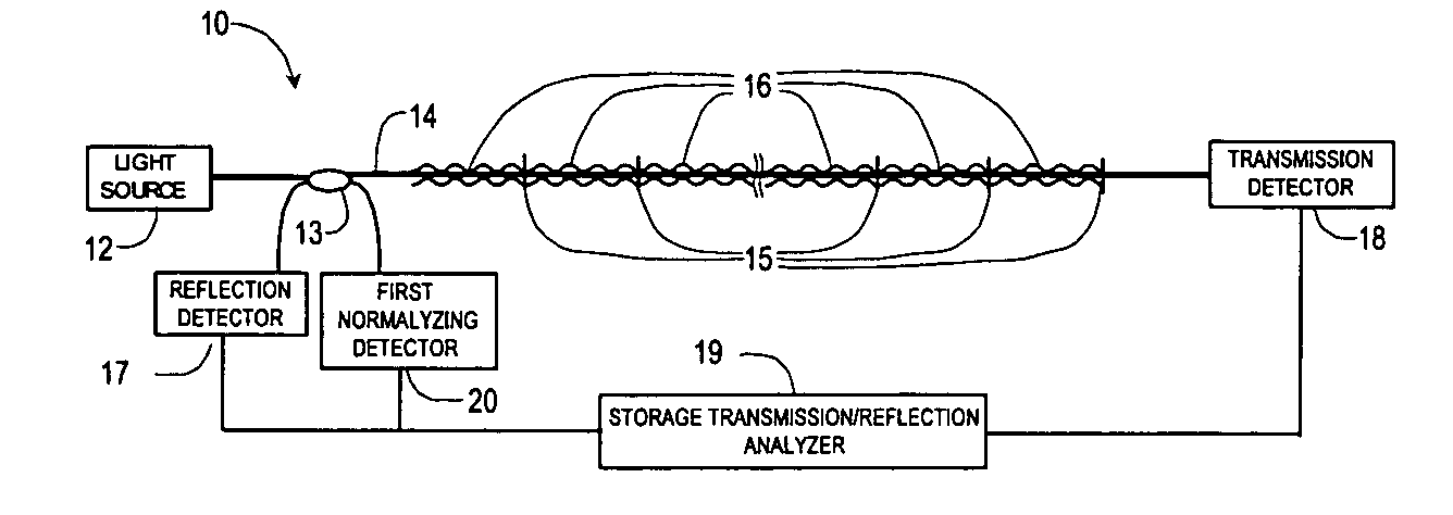
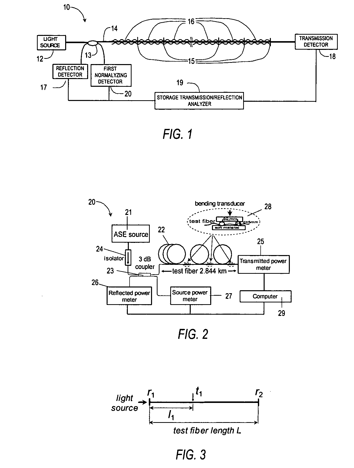
[0052] Referring to FIG. 1, the present invention comprises a distributed fiber optic sensor with storage transmission-reflection analyzer 10. The embodiment includes a light source 12 that may for example be a LED, laser or white light source, a test fiber 14, an optical transmission detector 17, and reflection detectors 18, which may, for example, be a photodiode. The light source 12 is operable to generate a light flux, which is launched into the test fiber 14 through the coupler 13.

[0053] The present invention can use standard telecommunication single or multimode silica or plastic fiber or any special light waveguide as said test fiber. The sensor is positioned along the structure to be monitored. The sensor 10 includes a plurality of loss-inducing members 16 characterized by a sensitivity to temperature, displacement, pressur...


PUM

PropertyMeasurementUnit
lengthaaaaaaaaaa
bending lossesaaaaaaaaaa
wavelengthaaaaaaaaaa

Abstract

This invention pertains to alarm condition fiber optic sensor with storage transmission-reflection analyzer for detection and localization of any number of consecutive loss-inducing disturbances along the test fiber. The sensor includes a test fiber having a first port and a second port; a light source for producing a beam of light propagating along the test fiber; a fiber optic beamsplitter having a first port connected to the light source, a second port connected to the first port of the test fiber, and a third and a fourth port; a plurality of reflectors positioned along the test fiber and a plurality of loss-inducing members positioned along the test fiber, wherein said each of the reflectors is matched to each loss-inducing members, wherein at least one reflector is placed between each consecutive loss-inducing members; an optical reflection detector to receive a light flux, the optical reflection detector connected to the third port of optic beamsplitter, wherein the reflection detector is adapted to sense changes in the average power of the light reflected from the reflectors; an optical transmission detector adapted to receive the light flux, connected to the second port of test fiber, said transmission detector being operable to sense changes in the average power of the light transmitted through the test fiber; and a storage transmission-reflection analyzer connected to reflection and transmission detectors, and adapted to measure time-behavior of the transmission-reflection dependencies of test fiber, said analyzer being operable to identify the locations and values of any number of consecutive loss-inducing disturbances along the test fiber by using stored locations and values of previous perturbations and the slope of dependence of normalized reflected average power versus the square of normalized transmitted average power for current loss-inducing perturbation.

Description

REFERENCE TO RELATED APPLICATIONS[0001] This application is a non-provisional of Provisional Application No. 60 / 451,534 filed Mar. 03, 2003.[0002] 1. Technical Field[0003] The present invention relates to optical fiber sensors and, more specifically, to distributed fiber optical sensors where an external perturbation such as temperature, pressure, displacement, etc, introduces additional losses at different locations along the sensing fiber. Particularly, this invention relates to a distributed optical fiber sensor suitable to be used as an alarm-conditions detector in industrial, military and civilian systems.[0004] 2. Description of the Related Art[0005] Distributed fiber optical sensors that can detect the loss-inducing perturbations are widely used in many different fields. For example, environmental sensors are used to detect pollutants and have become increasingly important as environmental standards. Chemical and petrochemical industry is another field where the use of sensor...

Claims


Application Information

Patent Timeline
Patent Type & Authority Applications(United States)
IPC IPC(8): G01D5/353G01L1/24G01M3/04G02B6/00
CPCG01L1/242G01L1/246G01D5/35377G01D5/35345G01D5/35354G01M3/047
Inventor SPIRIN, VASILII V.SHLYAGIN, MIKHAIL G.MIRIDONOV, SERGUEI V.MENDIETA JIMENEZ, FRANCISCO J.LUCERO, ALFREDO MARQUEZABENCHUCHAN, ENRIGUE MITRANI
Owner CENTRO DE INVESTIGACION CIENTIFICA Y DE EDUCACION SUPERIOR DE ENSENADA
Why Eureka
Try Eureka