
Method and system for downhole clock

a technology of a clock and a synchronization mechanism, applied in the field of well logging, can solve the problems of difficulty in synchronizing the two clocks to determine the propagation time of interrogating signals

Inactive Publication Date: 2004-12-09
HALLIBURTON ENERGY SERVICES INC
View PDF12 Cites 22 Cited by
  • Summary
  • Abstract
  • Description
  • Claims
  • Application Information

AI Technical Summary

Benefits of technology

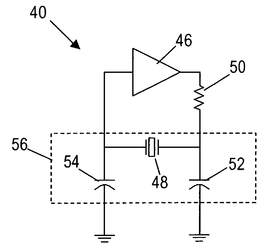
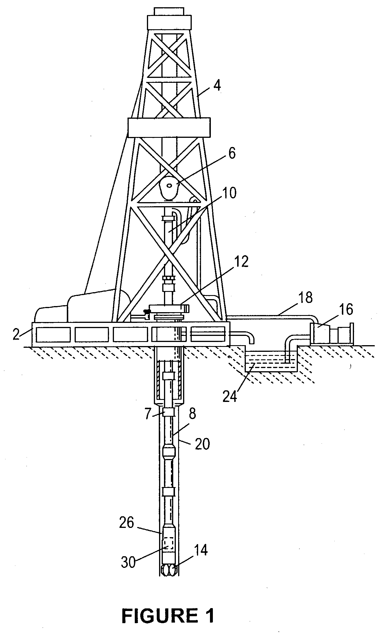
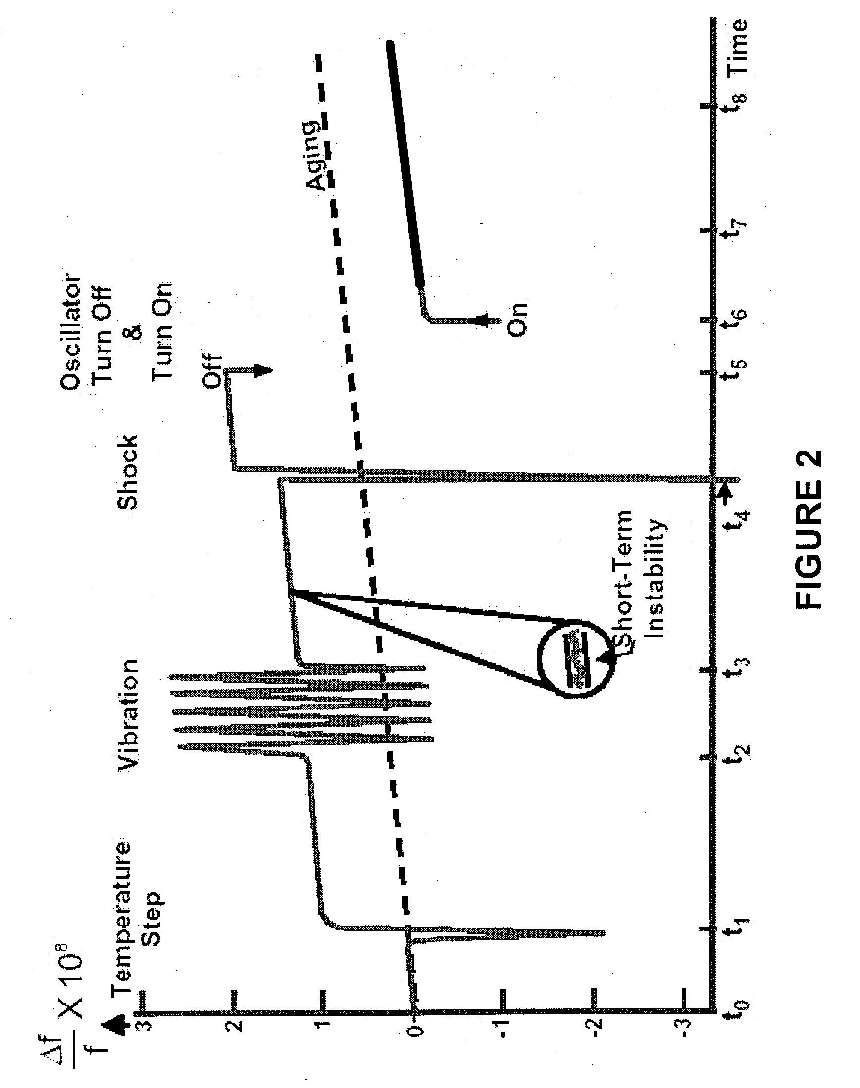
[0010] Accordingly, there is disclosed herein a method and apparatus for a downhole clock that is substantially insensitive to the factors that may cause frequency (and therefore time) deviation. In some embodiments, the downhole clock may include an oscillator and a temperature regulator. The oscillator may, in combination with other devices, provide a downhole clock for time-stamping downhole measurements, and the oscillator may include a crystal. The temperature regulator may maintain the oscillator within a predetermined temperature range so that the crystal's frequency deviations caused by temperature fluctuations are small. Also, the downhole clock's time may be compensated for the crystal's frequency deviation, possibly caused by aging.

Problems solved by technology

If the source energy originated from downhole, the transmission time and arrival time may be correlated by the same clock; however, if the energy originates from the surface (or other location), a second clock may also be used, which presents difficulty in synchronizing the two clocks to determine propagation time of the interrogating signals.

Method used


Image

  • Method and system for downhole clock
  • Method and system for downhole clock
  • Method and system for downhole clock

Examples


Embodiment Construction

[0010] Accordingly, there is disclosed herein a method and apparatus for a downhole clock that is substantially insensitive to the factors that may cause frequency (and therefore time) deviation. In some embodiments, the downhole clock may include an oscillator and a temperature regulator. The oscillator may, in combination with other devices, provide a downhole clock for time-stamping downhole measurements, and the oscillator may include a crystal. The temperature regulator may maintain the oscillator within a predetermined temperature range so that the crystal's frequency deviations caused by temperature fluctuations are small. Also, the downhole clock's time may be compensated for the crystal's frequency deviation, possibly caused by aging.

[0011] A better understanding of the present invention can be obtained when the following detailed description of the preferred embodiment is considered in conjunction with the following drawings, in which:

[0012] FIG. 1 illustrates a well durin...


PUM


Abstract

A downhole crystal-based clock that is substantially insensitive to the factors that cause frequency deviation. The clock may be maintained at a predetermined temperature using a temperature sensing device and a heating device, where the predetermined temperature corresponds to the temperature at which the crystal experiences only slight frequency deviation as a function of temperature. A microprocessor may monitor the clock and compensate for long-term aging effects of the crystal according to a predetermined algorithm. The predetermined algorithm may represent long-term aging effects of the crystal which were derived by comparing the crystal clock to a more accurate clock (e.g., an atomic clock) prior to placing the clock downhole. In this manner, the crystal-based clock may be substantially free from the factors that cause frequency, and therefore time variations.

Description

[0001] Not applicable.[0002] Not applicable.[0003] 1. Field of the Invention[0004] The preferred embodiments relate to well logging. More particularly, the preferred embodiments relate to generating a downhole clock for improving data measurements taken during logging.[0005] 2. Description of the Related Art[0006] Modern petroleum drilling and production operations demand a great quantity of information relating to parameters and conditions downhole. Such information may include characteristics of the earth formations traversed by the wellbore, along with data relating to the size and configuration of the borehole itself. The collection of information relating to conditions downhole, which commonly is referred to as "logging," may be performed by several methods.[0007] In conventional wireline logging, a probe or "sonde," housing formation sensors, may be lowered into the borehole after some or all of the well has been drilled. Once in the borehole, the sonde may be used to determin...

Claims


Application Information

Patent Timeline
Patent Type & Authority Applications(United States)
IPC IPC(8): E21B47/01H03L1/02
CPCE21B47/011H03L1/02E21B47/017E21B47/01H03L1/028
Inventor VARSAMIS, GEORGIOS L.ALTHOFF, GARY D.WISNIEWSKI, LAURENCE T.SCHMITT, DENIS P.ARIAN, ABBASDUDLEY, JAMES H.
Owner HALLIBURTON ENERGY SERVICES INC
Learn More