Apparatus for longitudinally orienting elongated wood strands

a technology of elongated wood strands and orienters, which is applied in special profiling/shaping machines, flat surfacing machines, profiling/shaping machines, etc., can solve the problems of unwanted deviation of noticeably lower strength characteristics, etc., and achieve the effect of improving the longitudinal orientation and improving the longitudinal orientation of the wood strands

Inactive Publication Date: 2004-12-16
DIEFFENBACHER GMBH & CO KG
View PDF9 Cites 3 Cited by
  • Summary
  • Abstract
  • Description
  • Claims
  • Application Information

AI Technical Summary

Benefits of technology

0020] The rotation shafts with their strand alignment chambers are referred to as chamber rollers. These chamber rollers with their paddle elements make sure that the wood strands to be oriented fall between axially spaced neighboring disks onto the paddle elements. Thus, the strands are forced to lie down, so to speak, on these paddle elements, thereby assuming a defined position relative to the longitudinal direction which corresponds to the feed advantage direction of the molding belt. As each of the chambers or rollers continues in its rotational motion, the respective wood strand begins, at a defined point, to slide off, beginning with its leading edge, the respective paddle element in the direction of the molding belt. When a strand has completely left its paddle element and has come to rest on the molding belt the large surface areas of a strand rest on the belt in parallel to the belt and longitudinally aligned therewith.
0021] As the leading ends of the wood strands contact the molding or conveyor belt they are either subjected to a braking action or they are accelerated depending on the speed of the molding belt and the instantaneous speed of the individual wood strand at the time of contacting the molding belt. In both instances each wood strand assumes the speed of the molding belt and is thereby pulled off the respective paddle element. This pulling off feature of the invention has the advantage of further improving the longitudinal orientation of the wood strands because each strand now still rests temporarily with its trailing edge on the respective paddle element, whereby the friction tends to turn, or rather align the chip with its longitudinal axis to the longitudinal feed advance direction of the molding belt.
0022] It has been found that a further improvement in the longitudinal orientation is achieved if the paddle elements have a V-shaped sectional configuration, whereby the wood strands are caused to slide toward a neighboring disk, where the strands comes to stop against the disk. As a result, the last degree of freedom of motion is eliminated and the wood strands lie with all three axes in a defined position on the paddle element.

Problems solved by technology

It has been found that a deviation of merely 10 to 15.degree. of the strand orientation from the longitudinal axis of the panel leads to noticeably lower strength characteristics.
Such deposition of the wood strands leads to unwanted deviations of the longitudinal alignment of the wood strands from the longitudinal axis of the board to be formed.

Method used


Image

  • Apparatus for longitudinally orienting elongated wood strands
  • Apparatus for longitudinally orienting elongated wood strands
  • Apparatus for longitudinally orienting elongated wood strands

Examples


Embodiment Construction

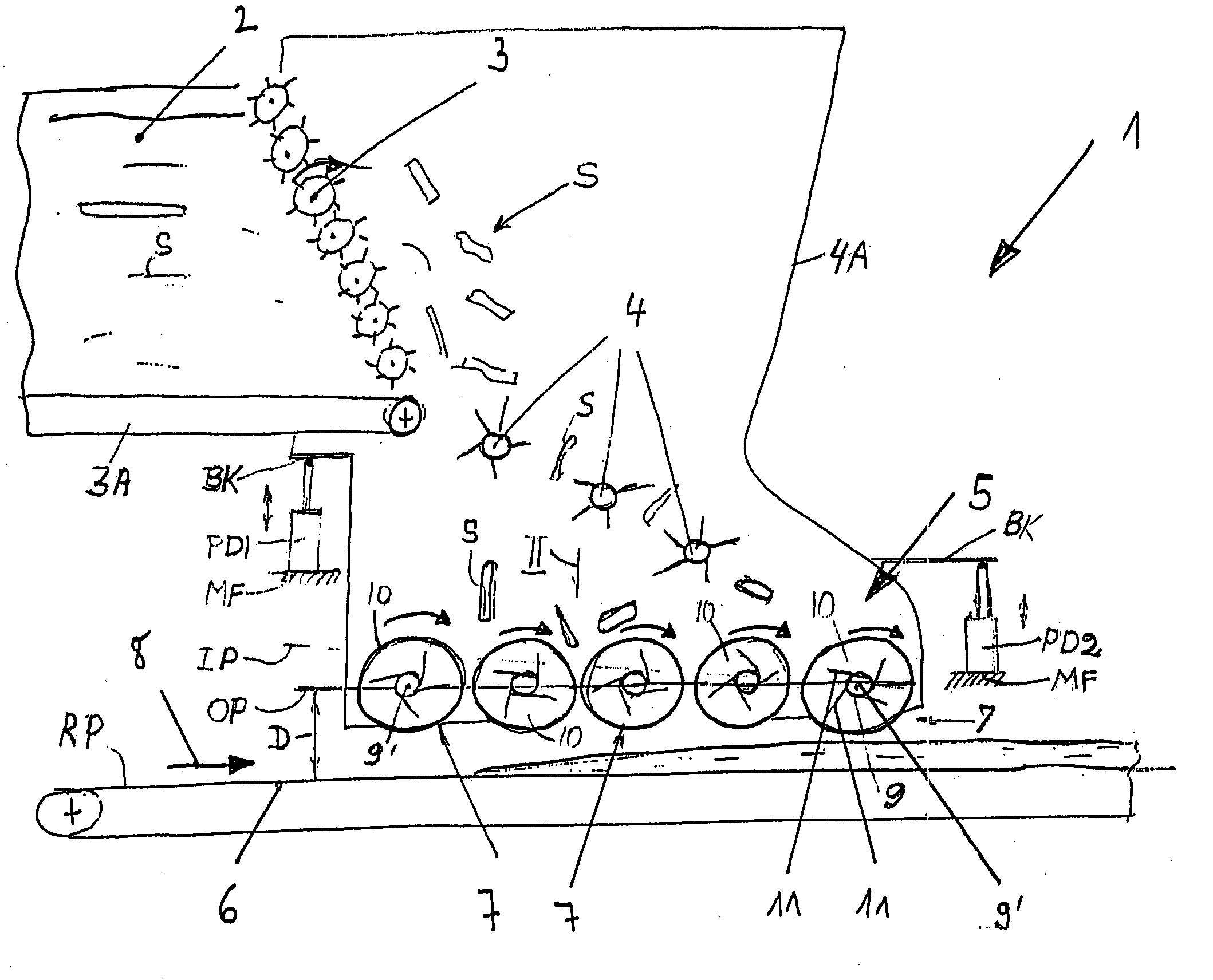
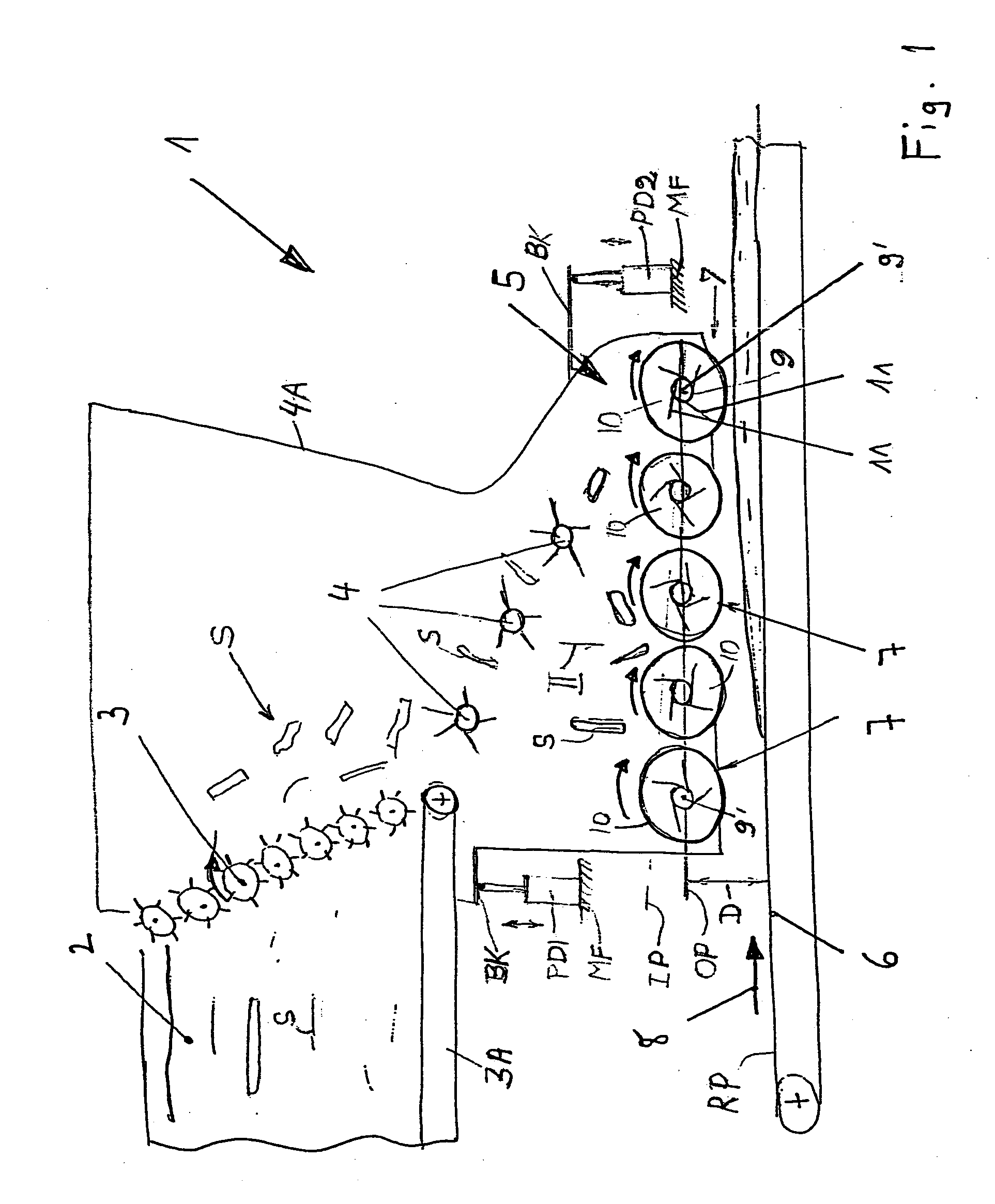
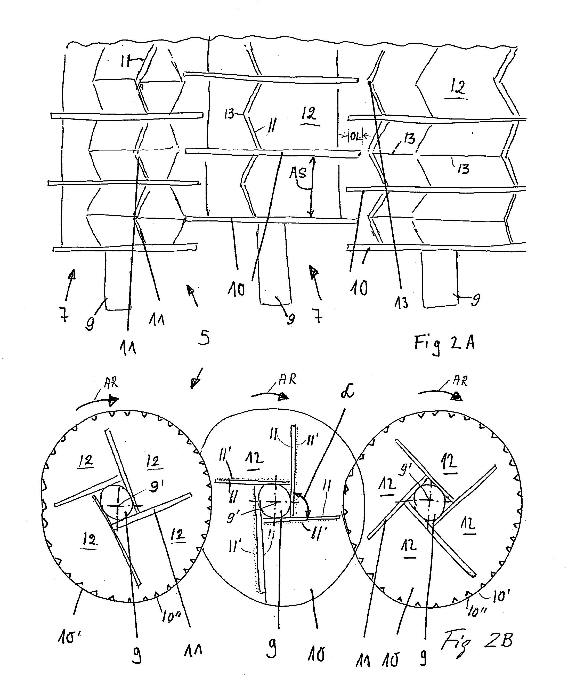
[0031] FIG. 1 shows schematically a side view of a panel molding station 1 with a wood strand supply bin 2 that functions as a dosing device. The output end of the supply bin 2 is formed by a strand discharge roller mechanism 3. Strands S are transported by a dosing conveyor 3A to the discharge roller mechanism 3. The strands S fall, by gravity, onto a strand distribution roller set 4 within a housing 4A. The roller set 4 distributes the strands S onto a strand alignment mechanism or head 5 that comprises a plurality of rotation shafts 9 having longitudinal rotational axes 9' arranged in parallel to one another. A molding conveyor belt 6 is positioned below the rotation shafts 9. The upper run of the molding conveyor belt 6 forms a reference plane RP.

[0032] As shown, the rotational shaft axes 9' are horizontally aligned in an orientation plane OP which is spaced from the reference plane RP by a distance D. A plurality of position adjustment devices PD1, PD2 support the housing 4A in...


PUM


Abstract

Elongated strands, particularly wood strands, are deposited on a molding belt or a conveyor belt so that the strands are longitudinally oriented relative to each other for manufacturing panels known as oriented strand boards. For this purpose the strands are discharged onto an alignment mechanism or head that has a plurality of rotation shafts each carrying a plurality of disks axially spaced from one another along the respective shaft. These disks form alignment channels when the shafts rotate. Each channel or channel section is further subdivided into strand alignment chambers by a plurality of paddle elements. Preferably four such paddle elements are mounted to the respective rotation shaft between two neighboring disks thereby forming four pass through chambers between two neighboring disks.

Description

PRIORITY CLAIM[0001] This application is based on and claims the priority under 35 U.S.C. .sctn.119 of German Patent Application 103 21 116.0, filed on May 9, 2003, the entire disclosure of which is incorporated herein by reference.[0002] 1. Field of the Invention[0003] The invention relates to the longitudinal orientation or alignment of elongated wood strands, particularly for producing panels in which the wood strands are pre-oriented. Such panels are known as OSB panels or as oriented strand boards which have a higher material strength than regular chip boards.[0004] 2. Background Information[0005] For manufacturing OSB panels long wood strands are deposited on a mold belt which is a conveyor belt that transports the oriented strands to a panel pressing operation. Conventionally, these wood strands have a length A of about 100 to 150 mm, a width B of about 10 to 30 mm, and a thickness C of about 0.4 to 1.0 mm. Conventionally, OSB panels have, as a rule, a three layer constructio...

Claims


Application Information

Patent Timeline
Patent Type & Authority Applications(United States)
IPC IPC(8): B27N3/14
CPCB27N3/143
Inventor GRAF, MATTHIAS
Owner DIEFFENBACHER GMBH & CO KG
Why Eureka
Try Eureka