Displays for high resolution images and methods for producing same

a high-resolution image and display technology, applied in printing, typewriters, instruments, etc., can solve the problems of insufficient practical application of electrochromic devices, low resolution, and multi-stage processing, and achieve high contrast and long-term stability of displays, suppress loss of electrochromophores, and cost-effective

Inactive Publication Date: 2004-12-16
NTERA LTD (IE)
View PDF42 Cites 35 Cited by
  • Summary
  • Abstract
  • Description
  • Claims
  • Application Information

AI Technical Summary

Benefits of technology

[0021] It is object of this invention to provide electrode constructions, and other components for incorporation into electrochromic displays, electrochromic displays demonstrating high resolution switchable images, either fixed or variable, that do not require photolithographic steps to define and structure the electrochromic material. Suitably the methods allow the patterning of (transparent) conductive electrodes. It is another object of this invention to disclose a practical, cost-effective process for preparing high-resolution electrochromic displays. Transmissive displays are desirable in particular transmissive sandwich structure displays. A further object of the present invention is to provide techniques / devices that provide high contrast and long term stability of the displays, i.e. techniques that suppress loss of the electrochromophores into the bulk of the electrolyte solution.

Problems solved by technology

The process being multistage is thus relatively cumbersome and expensive.
The performance of polymers such as those described in electrochromic devices is not satisfactory for practical applications in displays.
Such systems allow for the display of graphical information, however the resolution is limited by the need to address each segment individually, and no means to prepare images with higher resolution is described.
It is believed that with this construction the device cannot be transmissive.
This may limit the ultimate aspect ratio of the display.
However the nature of screen printing, namely the pressing of paste through a mesh, limits the resolution achievable, and resolutions of the order of 300 ppi or above are not possible.
In addition, the architecture proposed in these inventions is not directly compatible with technologies providing fast switching speed.
This presents a problem in trying to provide more rapid techniques for the chemical modification of substrates such as for example the application of elecrochromic material.
Lateral migration tends to reduce resolution.
Immersion techniques tend to be complicated and relatively expensive.

Method used


Image

  • Displays for high resolution images and methods for producing same
  • Displays for high resolution images and methods for producing same
  • Displays for high resolution images and methods for producing same

Examples


example 1

[0300] Working Electrode with a Direct Positive One Colour Electrochrome Print (Case 1a)

[0301] Preparation of the Conductive Glass:

[0302] A TEC glass (70.times.70.times.2.2 mm) was immersed in aqueous NaOH / isopropanol solution for several hours, washed with distilled water and dried.

[0303] TiO.sub.2-coating of the Conductive Glass:

[0304] The clean TEC glass was coated with a colloidal solution of TiO.sub.2 using the doctor blade method, as described in the literature. R. Cinnsleach et al., Sol. Energy Mater. Sol Cell 1998, 55.215.

[0305] Preparation of Electrochromic Ink:

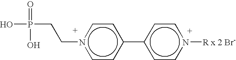
[0306] A solution of 0.1 M N-(Phosphono-2-ethyl)-N'-ethyl-4,4'-bipyridiniu-m dibromide in 68 vol % water, 25 vol % methanol and 7 vol % glycerine was prepared.

[0307] Image Editing:

[0308] A gray scale Windows.RTM. bitmap with 300 ppi resolution was converted with Corel Photo Paint (V. 9) to 1 bit colour depth using the Jarvis algorithm. The graphic was then transformed into the negative and imported to CorelDraw.RTM. ...

example 2

[0315] Working Electrode with a Masked One Colour Electrochrome Print (Case 2)

[0316] Preparation of the Conductive Glass:

[0317] As described in Example 1.

[0318] TiO.sub.2-coating of the Conductive Glass:

[0319] As described in Example 1.

[0320] Preparation of Ink for Masking:

[0321] The n-octylphosphonic acid was prepared according to the literature reference Kosolapoff, G. M., "Isomerization of Alkylphosphites. III. The Synthesis of n-Alkylphosphonic Acids", J. Am. Chem. Soc. (1945) 67, 1180-1182.

[0322] A solution of 0.2 M n-octylphosphonic acid in 65 vol % ethylene glycol, 20 vol % methanol and 15 vol % water was prepared.

[0323] Image Editing:

[0324] A gray scale Windows.RTM. bitmap with 300 ppi resolution was converted with Corel Photo Paint (V. 9) to 1 bit colour depth using the Jarvis algorithm. The graphic was then imported to CorelDraw.RTM. (V. 9). Afterwards the white pixels were converted to be transparent and the black pixels were turned to white. Finally, a rectangle of pure ...

example 3

[0331] Working Electrode with a Direct Positive One Colour TiO.sub.2 Print (Case 3)

[0332] Preparation of the Conductive Glass:

[0333] As described in Example 1.

[0334] Preparation of the Ceramic Ink.

[0335] 3 ml of an aqueous colloidal solution (15 w-% TiO.sub.2 as described in EP 0 958 526 was diluted with 2 ml of a solution of 25 vol % MeOH in distilled water.

[0336] Image Editing:

[0337] As described in Example 1.

[0338] Ceramic Printing (FIG. 1):

[0339] The clean conductive glass was put into the caddy using the adapter. The diluted colloidal was filled into the vessel sitting on the cyan conection sleeve. Several sequential purge cycles were manualy triggered. The jet of the colloid was checked before printing. The image was then printed using the Epson.RTM. Stylus Color 440 driver for Windows NT.RTM. 4.0 Version 3 (driver settings: normal paper, 720 dpi, colour mode, other parameters default). Afterwards the solvent was removed with a hot-air blower. The printing was repeated one tim...


PUM

PropertyMeasurementUnit
timeaaaaaaaaaa
crystallite sizeaaaaaaaaaa
thicknessaaaaaaaaaa

Abstract

An electrode construction for incorporation into an electrochromic display device with a substrate; an electrochromic material applied to the substrate in a spatially resolved manner. The electrochromic material is (a) applied to the substrate with a resolution of greater than about 75 dpi and (b) the spatial resolution is obtained by a non-photolithographic method. The substrate may have a mesoporous morphology. Printing methods such as ink-jet printing may be used. Other materials such as masking materials, charge storing materials, complementary electrochromic materials and the mesoporous material itself may be set down by ink-jet methods. The electrodes construction may be included in electrochromic devices. The resolution obtained is high and devices incorporating these materials may be addressable.

Description

[0001] The present invention relates to displays displaying high resolution information, in particular to electrochromic displays displaying high resolution information, either in the form of fixed or variable images. The invention also relates to methods for depositing the electrochromic materials onto the substrates and to display created by these methods. The present invention further relates to displays employing large surface area materials especially mesoporous materials. An important type of mesoporous materials are constructed of fused particles (usually nanoparticles) which are typically of a size measured in nanometers. If the fused particles are crystalline in nature (they may be amorphous) then the material is often referred to as nanocrystalline. The mesoporous materials employed herein may be nanocrystalline but are in any case constructed of nanoparticles. Desirably the materials are nanocrystalline and are more preferably in the form of a thin film. The invention als...

Claims


Application Information

Patent Timeline
Patent Type & Authority Applications(United States)
IPC IPC(8): G02F1/155B41J2/01B41J3/407C09K9/02G02F1/1503G02F1/153
CPCB41J3/407G02F1/1521G02F1/1533G02F2001/151G02F2202/023G02F2001/1518G02F1/1503
Inventor WALDER, LORENZMOLLER, MARTIN
Owner NTERA LTD (IE)
Why Eureka
Try Eureka