Eureka AIR delivers breakthrough ideas for toughest innovation challenges, trusted by R&D personnel around the world.

Cooling device and optical device and projector having the cooling device

a cooling device and optical device technology, applied in static indicating devices, instruments, television systems, etc., can solve the problems of inability to efficiently cool down the illuminance of the light source, the heat of the optical device that increases in accordance, and the inability to form a clear imag

Inactive Publication Date: 2004-12-23
SEIKO EPSON CORP
View PDF7 Cites 16 Cited by
  • Summary
  • Abstract
  • Description
  • Claims
  • Application Information

AI Technical Summary

Benefits of technology

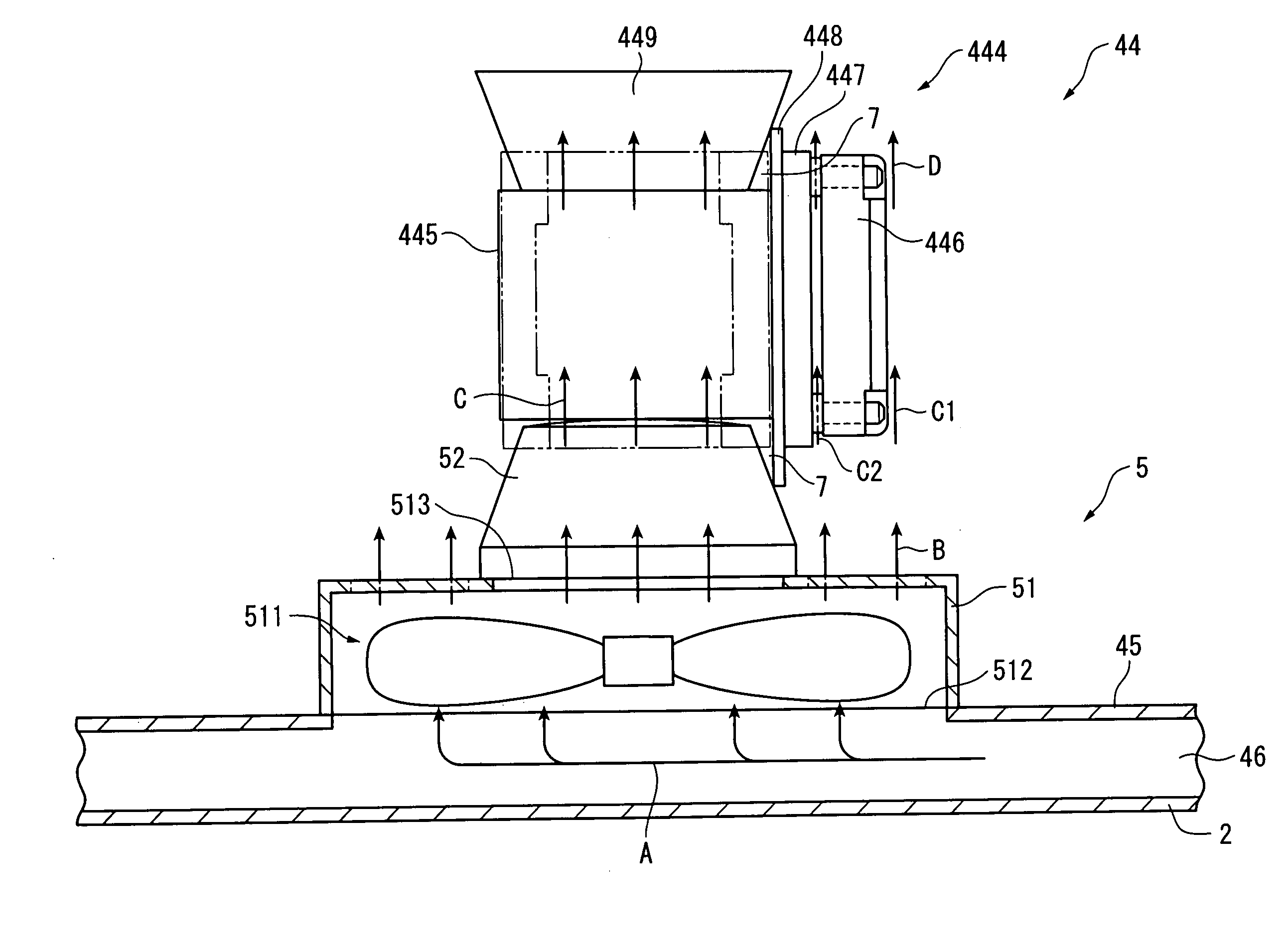
[0010] According to the above arrangement, the heat generated on the object to be cooled is conducted to the chassis of the cooling device, which is radiated by the heat radiator of the cooling device. According to the above arrangement, the object is cooled by two cooling systems, i.e. the cooling air blown from the fan body and heat radiation by the heat radiator after being thermally conducted to the chassis of the cooling device. Accordingly, the object can be efficiently cooled.
[0030] According to the above arrangement, the cooling air to be used for cooling the object to be cooled by the cooling device is transferred by the sirocco fan. When the cooling device is provided on the optical device and an axial-flow fan is used for the cooling device, since it is required for the cooling device to transfer the cooling air simultaneously to the plurality of optical modulators attached to the color-combining optical system to cool the components, an axial-flow fan having large air-blowing area is preferably used. On the other hand, a sirocco fan has a great discharge pressure with low revolution number, which has excellent silentness as compared to axial-flow fans. According to the above arrangement, the cooling device can be located remote from the intake opening and the jet noise of the axial-flow fan of the cooling device does not leak to the outside of the projector, where the external air is drawn in by the silent sirocco fan and the external air is transferred to the axial-flow fan with a high discharge pressure, thereby securely cooling the optical device. Accordingly, the object to be cooled such as the optical device can be efficiently cooled and the silentness of the projector can be improved.

Problems solved by technology

Further, a clear image cannot be formed unless the image formation area of the optical modulator is located at the back-focus position of the projection lens.
However, in the above optical device, since the optical device is cooled only by the air blown by the cooling fan, the heat of the optical device that increases in accordance with intensifying illuminance of the light source cannot be efficiently cooled.

Method used


Image

  • Cooling device and optical device and projector having the cooling device
  • Cooling device and optical device and projector having the cooling device
  • Cooling device and optical device and projector having the cooling device

Examples


first embodiment

[0039] [1. First Embodiment]

[0040] (1) Exterior Arrangement

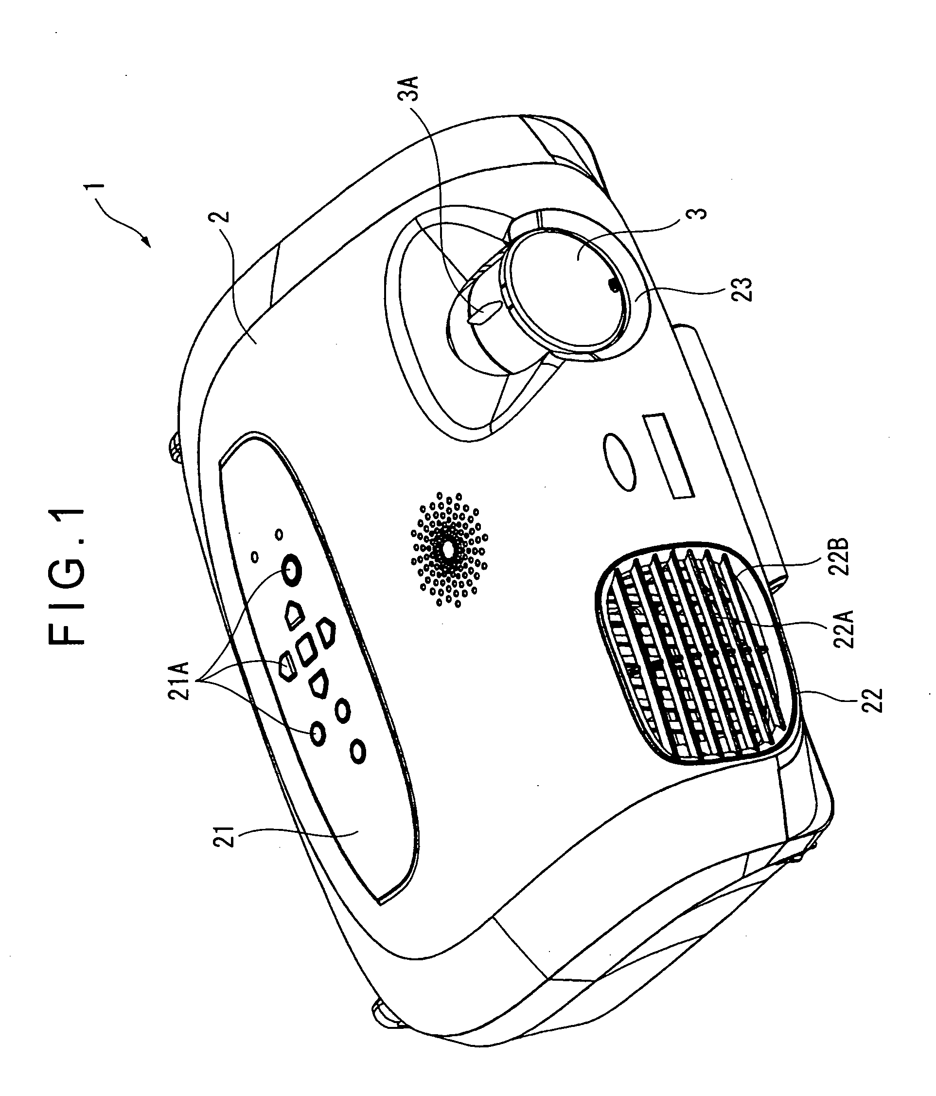
[0041] FIG. 1 shows a projector according to the first embodiment. The projector 1 modulates a light beam irradiated by a light source in accordance with image information and projects the light beam on a projection surface such as a screen in an enlarged manner. As shown in FIGS. 1, the projector 1 has an exterior case 2 and a projection lens 3 exposed from the exterior case 2.

[0042] The exterior case 2 is a synthetic resin exterior casing, which houses the body of the projector 1. An operation panel 21 provided with a plurality of switches 21A for actuating and adjusting the projector 1 is provided on the upper side of the exterior case 2. An exhaust port 22 is formed on the front left side (seen from the front side) of the exterior case 2. An exhaust fan (not shown) is disposed inside the exhaust outlet 22, the exhaust fan discharging the air having cooled the inside of the projector 1 from the exhaust port 22 to the outs...

second embodiment

[0104] [2. Second Embodiment]

[0105] Next, a projector according to a second embodiment of the present invention will be described below. The projector of the second embodiment has approximately the same arrangement as the projector described in the first embodiment except that an attaching portion for attaching the projection lens is integrally formed on the cooling device for cooling the optical device. Incidentally, in the following description, the same reference numerals will be attached to the same or approximately the same components as the above-described components to omit the description thereof.

[0106] FIG. 7 shows a cooling device 5A provided on the projector 1 according to the second embodiment. The cooling device 5A is arranged approximately in the same manner as the cooling device 5, which includes the frame 51 (chassis) that accommodates the fan body 511, and the base portion 52 integrally formed on the frame for supporting the cross dichroic prism 445 of the optical d...


PUM

PropertyMeasurementUnit
heat-conductiveaaaaaaaaaa
opticalaaaaaaaaaa
areaaaaaaaaaaa

Abstract

A cooling device (5) has a frame (51) as a chassis having a fan body (511) thereinside and a base portion (52) formed on the upper side of the frame (51), the frame (51) and the base portion (52) being made of a heat-conductive material. An object (44) to be cooled is fixed on the base portion (52) and heat is conducted from the object (44) to the base portion (52) where the conducted heat is radiated. The fan body (511) provided on the cooling device (5) blows a cooling air to cool the object (44). Accordingly, the heat on the object (44) is cooled by the cooling air blown by the fan body (511) and also by the heat-radiation by a heat radiator on the cooling device (5).

Description

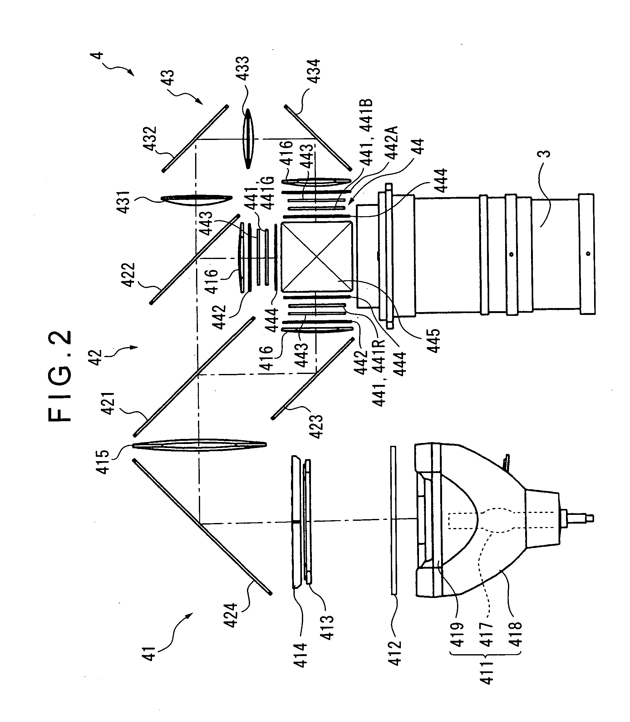
[0001] 1. Field of the Invention[0002] The present invention relates to a cooling device including a fan having a frame, and an optical device and a projector having the cooling device.[0003] 2. Description of Related Art[0004] Conventionally, projectors that modulate a light beam irradiated by a light source in accordance with image information to form an optical image and projects the image in an enlarged manner have been used for presentations at conferences, scientific meetings, exhibitions and the like and for so-called home-theaters. Three-plate projectors have been known as such projectors. The three-plate projectors each have a light source, a color-separating optical system that separates the light beam irradiated by the light source into a plurality of color lights, a plurality of optical modulators that modulates the respective color lights separated by the color-separating optical system, a color-combining optical system that combines the light beam modulated by the resp...

Claims


Application Information

Patent Timeline
Patent Type & Authority Applications(United States)
IPC IPC(8): G02F1/13G02B27/18G02F1/133G02F1/1333G03B21/00G03B21/14G03B21/16H04N5/74
CPCG02F1/133385H04N5/7441H04N9/3141H04N9/3144G03B21/16
Inventor KITABAYASHI, MASASHI
Owner SEIKO EPSON CORP
Why Eureka
Eureka Blog
Learn More