Multi-mode multi-amplifier architecture

a multi-amplifier and amplifier technology, applied in the field of amplifier architecture or system, can solve the problems of inefficient linear amplifier operation in these types of signals, general non-operation at high efficiency, and additional challenges

Inactive Publication Date: 2004-12-30
NORTHROP GRUMMAN SYST CORP
View PDF8 Cites 131 Cited by
  • Summary
  • Abstract
  • Description
  • Claims
  • Application Information

AI Technical Summary

Benefits of technology

0008] The present invention relates to an amplification architecture or system that switches between operation in a component mode and a composite mode. In the component mode, the components of an input signal are ...

Problems solved by technology

However, they are generally not operated at high efficiency due to the need to provide high linearity.
Time varying envelopes present an additional challenge.
Thus, there is customarily an inherent tradeoff between linearity and efficiency in amplifier designs.
Therefore, the operation of the linear amplifiers in these types of signals is very inefficient, since the amplifiers must have their supply voltage sized to handle the large peak voltages even though the signals are much smaller a substantial portion of the time.
Additionally, the size and cost of the power amplifier is generally proportional to the required peak output power of the amplifier.
The cost of the amplifier scales with its, peak power.
Several other circuit costs including heat sinks and DC-DC power supplies scale inversely to peak power and dissipated heat (which results from the electrical inefficiency).
Related base station costs of AC-DC power supplies, back-up batteries, cooling, and circuit breakers also scale inversely with efficiency as does the elect...

Method used


Image

  • Multi-mode multi-amplifier architecture
  • Multi-mode multi-amplifier architecture
  • Multi-mode multi-amplifier architecture

Examples


Embodiment Construction

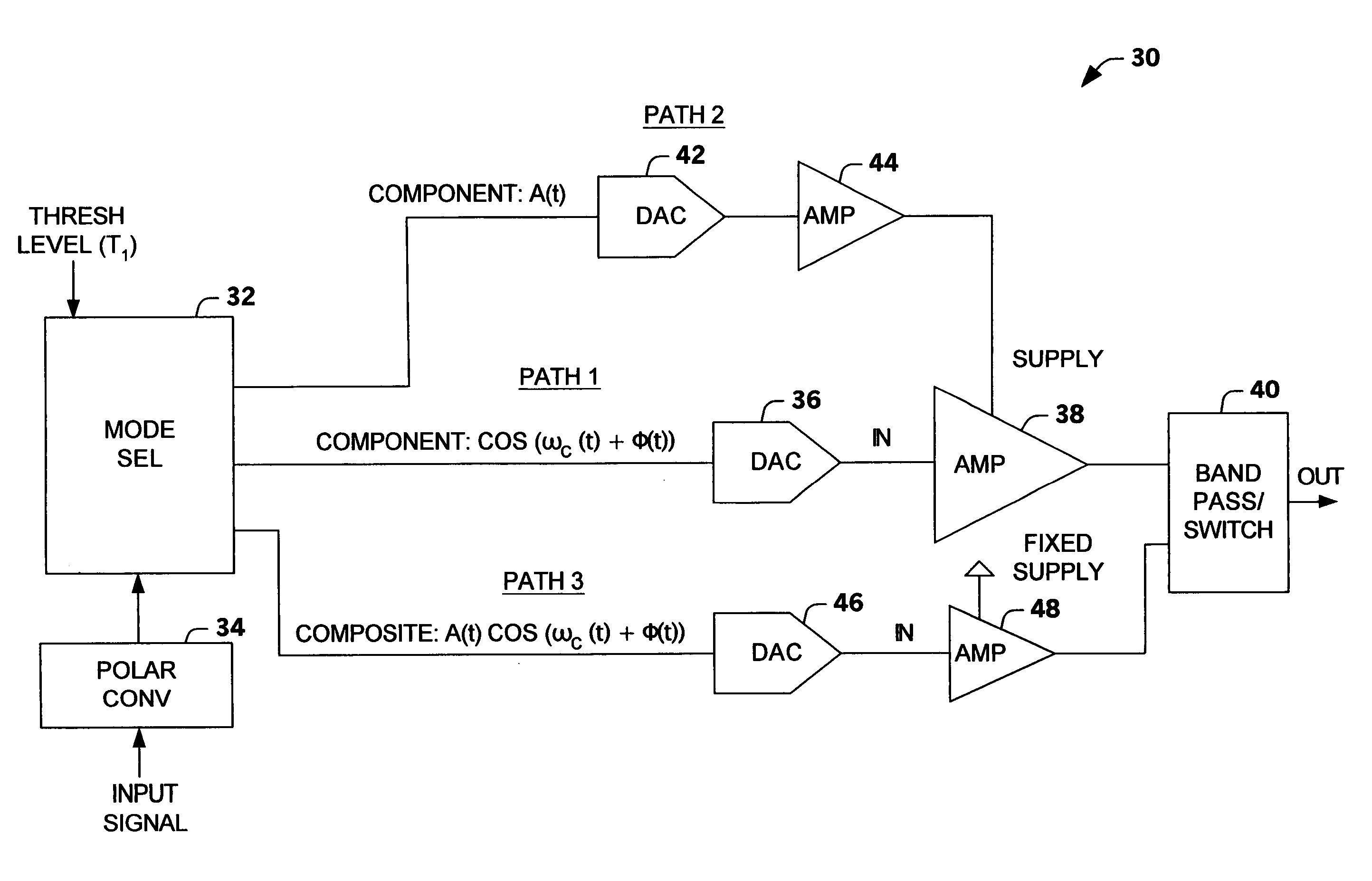
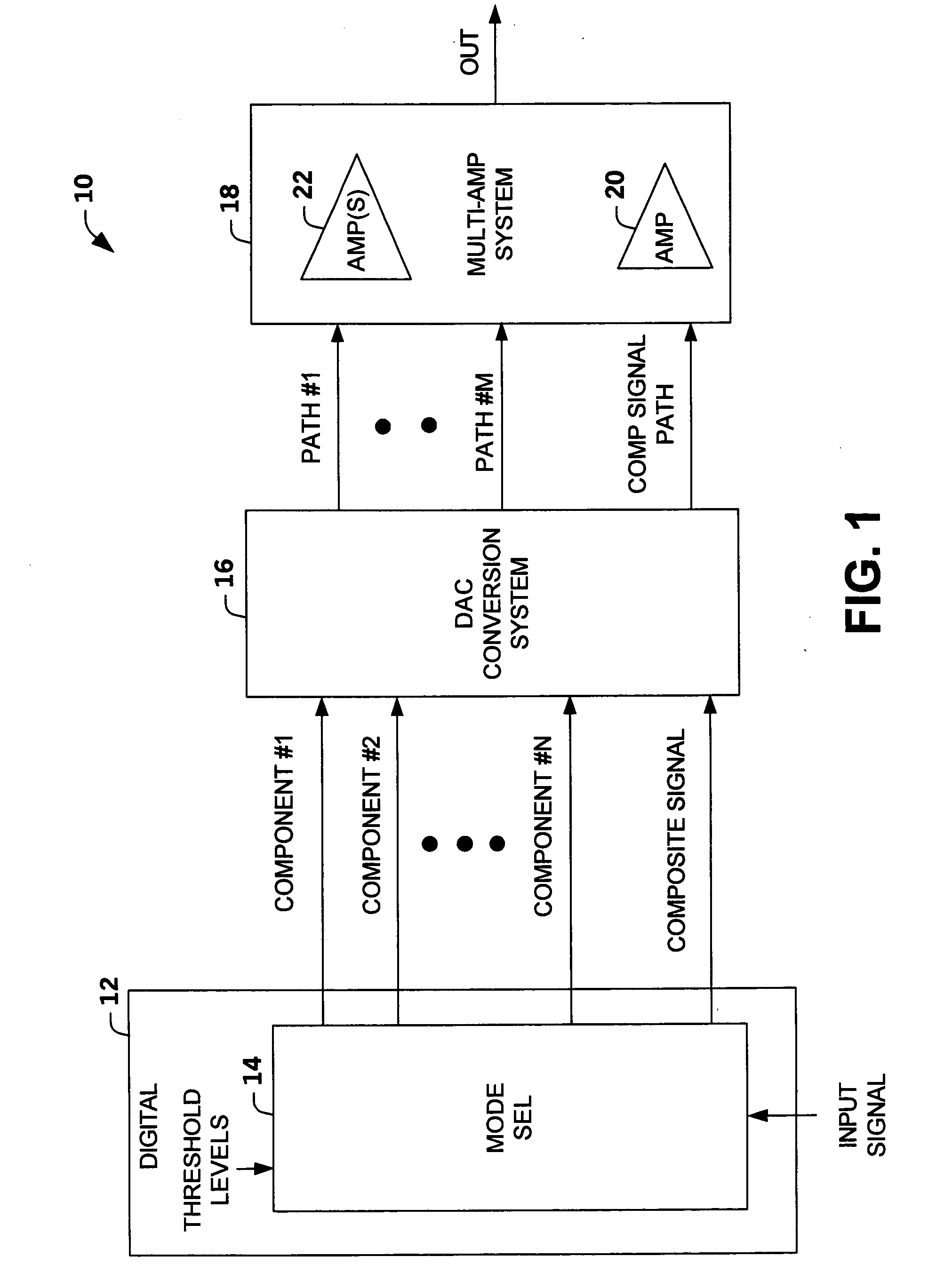
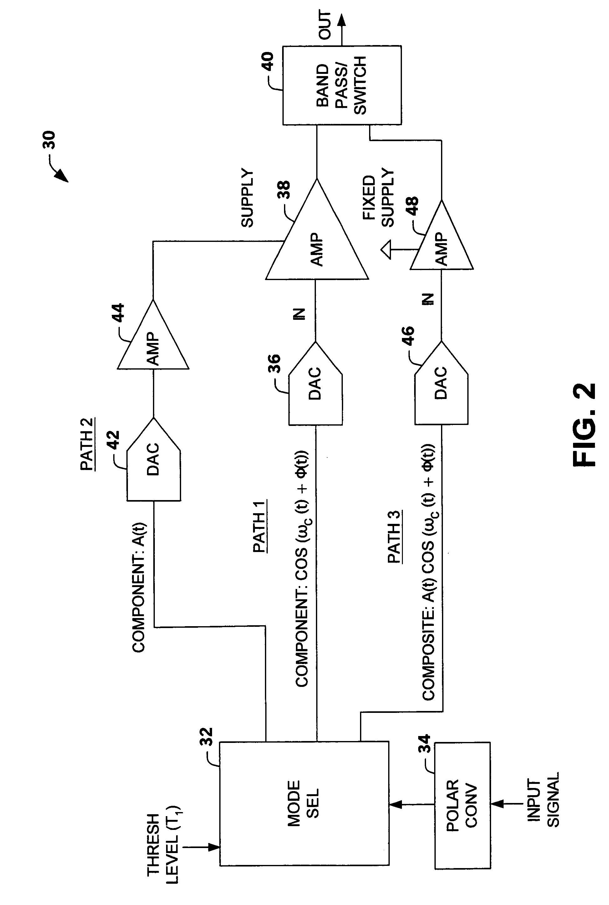
[0021] The present invention relates to an amplification system or architecture that switches between operation in a component mode and a composite mode based on a characteristic of an input signal relative to a transition point or threshold level (e.g., envelope amplitude level, digital count representation of signal level, power amplifier power level). In the component mode, an input signal is separated into two or more components and transmitted to one or more amplifiers. In the composite mode, a composite signal is amplified via an amplifier (e.g., a linear amplifier). A mode selector controls whether components ("component mode") of the signal are provided to the one or more amplifiers or whether the composite signal ("composite mode") is provided to the amplifier.

[0022] FIG. 1 illustrates an amplification system or architecture 10 in accordance with an aspect of the present invention. The amplification system 10 switches operation between a component mode and a composite mode ...


PUM


Abstract

An amplification architecture or system is provided having a multiple amplifier system that switches modes of operation between operation in a component mode and a composite mode based on a characteristic of an input signal relative to a threshold level. In the component mode, the components of the input signal are employed to different terminals of the multiple amplifier system that provide a reconstructed amplified representation of the input signal. In the composite mode, the input signal is amplified to provide an amplified representation of the input signal.

Description

[0001] The present invention relates generally to electronic devices, and more particularly to an amplifier system that operates in multiple modes.[0002] RF power amplifiers used for wireless communication transmitters, with spectrally efficient modulation formats, require high linearity to preserve modulation accuracy and to limit spectral regrowth. Typically, a linear amplifier, Class-A type, Class-AB type or Class-B is employed to faithfully reproduce inputs signals and to limit the amplifier output within a strict emissions mask. Linear amplifiers are capable of electrical (DC power in to RF power out or DC-RF) efficiencies greater than 50% when operated at saturation. However, they are generally not operated at high efficiency due to the need to provide high linearity. For constant envelope waveforms, linear amplifiers are often operated below saturation to provide for operation in their linear regime. Time varying envelopes present an additional challenge. The general solution...

Claims


Application Information

Patent Timeline
IPC IPC(8): H03F3/68H03F1/02H03F1/07H03F1/32H03F3/72H04B1/04
CPCH03F1/0244H03F1/0288H03F1/3241H03F3/72H03F2200/198H03F2200/331
Inventor ROBINSON, IANWINTER, FRANK
Owner NORTHROP GRUMMAN SYST CORP
Why Eureka
Try Eureka