Adaptive beam forming antenna system using a tunable impedance surface

a beam forming antenna and impedance surface technology, applied in the direction of antennas, electrical equipment, etc., can solve the problems of high cost of adaptive antenna methods compared to the present disclosure, the complexity of adaptive antenna methods is high, and the cost of phased arrays is typically high

Active Publication Date: 2004-12-30
HRL LAB
View PDF99 Cites 191 Cited by
  • Summary
  • Abstract
  • Description
  • Claims
  • Application Information

AI Technical Summary

Problems solved by technology

(1) The tunable impedance surface, invented at HRL Laboratories of Malibu, Calif. See, for example, the following U.S. Pat. Nos.: 6,483,480; Sievenpiper, and Sievenpiper, 6,538,621. The tunable impedance surface is described in various incarnations, including electrically and mechanically tunable versions. However, the tuning technology disclosed herein is different in that relates to a tuning method that allows for the independent control of the phase preferably at each element of the tunable impedance surface.
(2) Phased array antennas. These are described in numerous patents and publications, and references. See, for example, U.S. patents by Tang, U.S. Pat. No. 4,045,800; Fletcher, U.S. Pat. No. 4,119,972; Jacomini, U.S. Pat. No. 4,217,587; Steudel, U.S. Pat. No. 4,124,852; and Hines, U.S. Pat. No. 4,123,759. Phased array antennas are typically built as arrays of independent receiving elements, each with a phase shifter. Signals are collected from each element and combined with the appropriate phase to form a beam or null in the desired direction. The disadvantage of the phased array compared to the present technology is that it is prohibitively expensive for many applications.
(3) Adaptive antennas. These are also described in numerous patents and publications, and references. See, for example, U.S. Patents by Daniel, U.S. Pat. No. 4,236,158; Marchand, U.S. Pat. No. 4,220,954; McGuffin, U.S. Pat. No. 4,127,586;

Method used


Image

  • Adaptive beam forming antenna system using a tunable impedance surface
  • Adaptive beam forming antenna system using a tunable impedance surface
  • Adaptive beam forming antenna system using a tunable impedance surface

Examples


Embodiment Construction

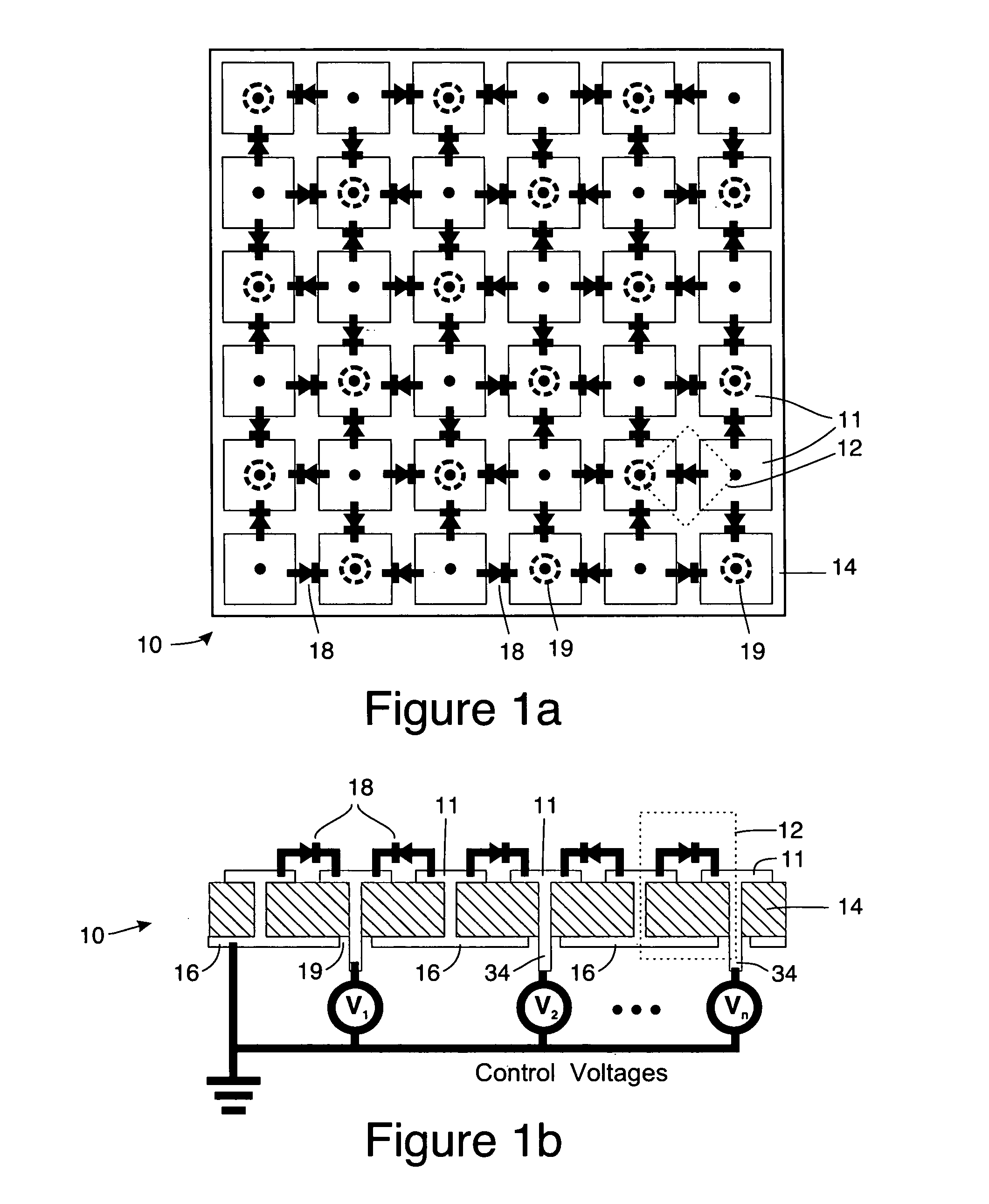
[0037] The technology disclosed herein preferably utilizes a tunable impedance surface, which surface has been disclosed in previous patents and patent applications noted above. An embodiment of an electrically tunable version of such a surface 10 is shown in FIGS. 1a and 1b. The tunable impedance surface 10 is preferably constructed as an array of small (much less than one wavelength in size on a side thereof) resonators cells 12 each of which can be considered as a LC circuit with an inductance L and a capacitance C. The array of resonator cells 12 are preferably defined by an array of plates 11 disposed on a dielectric surface 14 and in close proximity to a ground plane 16 (typically the dielectric surface has a thickness less than one tenth of a wavelength as the frequency of interest). This surface 10 is tuned using resonator tuning elements or means such as varactor diodes 18 that provide a variable capacitance that depends on a control voltage V.sub.1, V.sub.2 . . . V.sub.n. ...


PUM


Abstract

A method of and apparatus for beam steering. A feed horn is arranged so that the feed horn illuminates a tunable impedance surface comprising a plurality of individually tunable resonator cells, each resonator element having a reactance tunable by a tuning element associated therewith. The tuning elements associated with the tunable impedance surface are adjusted so that the resonances of the individually tunable resonator cells are varied in a sequence and the resonances of the individually tunable resonator cells are set to values which improve transmission of information via the tunable impedance surface and the feed horn.

Description

CROSS REFERENCE TO RELATED APPLICATIONS AND PATENTS[0001] This application claims the benefit of U.S. Provisional Patent Application No. 60 / 470,029 filed May 12, 2003.[0002] This application is related to the following U.S. patent applications: U.S. patent application Ser. No. 09 / 537,923 filed Mar. 29, 2000 (now U.S. Pat. No. 6,538,621) and U.S. patent application Ser. No. 09 / 589,859 filed Jun. 8, 2000 (now U.S. Pat. No. 6,483,480). The disclosures of these two applications are incorporated herein by reference.[0003] This application is related to the disclosure of U.S. Pat. No. 6,496,155 to Sievenpiper et al., which is hereby incorporated by reference. This application is also related to the disclosure of U.S. Provisional Patent Application Ser. No. 60 / 470,028 filed on May 12, 2003 entitled "Steerable Leaky Wave Antenna Capable of Both Forward and Backward Radiation" and to the disclosure of U.S. Provisional Patent Application Ser. No. 60 / 470,027 filed on May 12, 2003 entitled "Met...

Claims


Application Information

Patent Timeline
IPC IPC(8): H01Q3/00H01Q3/24
CPCH01Q3/46H01Q19/104
Inventor SIEVENPIPER, DANIEL F.SCHAFFNER, JAMES H.TANGONAN, GREGORY L.
Owner HRL LAB
Why Eureka
Try Eureka