Construction equipment

a construction equipment and equipment technology, applied in the direction of constructions, soil shifting machines/dredgers, etc., can solve the problems of reduced driving performance of the vehicle, increased vehicle weight, reduced visibility to the front, above and to the rear of the operator's cab, etc., to facilitate attaching and detaching operations, simple structure, and low cost

Inactive Publication Date: 2005-01-06
KOMATSU LTD
View PDF11 Cites 20 Cited by
  • Summary
  • Abstract
  • Description
  • Claims
  • Application Information

AI Technical Summary

Benefits of technology

[0014] (2) Since the operator's cab protection frame including the operator's cab protection member has a simple structure, and is only provided upright in the vertical direction behind the operator's cab, the operator's cab protection frame can be applied to compact to large construction equipment easily at low cost. Since the number of components of the operator's cab protection frame is small and the number of mounting locations is small, attaching and detaching operations are facilitated.
[0015] (3) For the same reason as item (2), the operator's cab protection member can be provided without increasing the outside dimension of the construction equipment, and therefore transportability of the construction equipment is not reduced.
[0016] (4) The operator's cab protection frame including the operator's cab protection member is only provided behind the operator's cab, and therefore the visibility to the front, to the sides, and to above from the operator's cab can be enhanced.
[0017] In the construction equipment, the operator's cab protection frame may be mounted to a vertical plate member of the upper revolving superstructure frame. According to this constitution, the operator's cab protection frame is mounted to the vertical plate member of the vehicle body frame (the upper revolving superstructure frame of the hydraulic shovel), and therefore the attaching and detaching operations are easily performed from above the construction equipment. As a result, assembling and disassembling operability and attachability and detachability of the operator's cab protection frame can be enhanced.
[0018] In the construction equipment, the operator's cab protection frame may be mounted to an upper portion of the counterweight. According to this constitution, the operator's cab protection member can be provided by using the counterweight as the mounting portion even when it is difficult to mount the operator's cab protection frame on the upper revolving superstructure frame because the area on the upper revolving superstructure frame is small as in the rearward small revolving type hydraulic excavator in which the revolving radius of the rear end portion is approximately within the vehicle width, for example. As a result, even in the case of the rearward small revolving type hydraulic excavator, the assembling and disassembling operability and transportability are not impaired. As a result, the strong operator's cab protection frame can be also provided in the compact construction equipment easily at low cost.
[0019] According to the above constitutions according to the present invention, the construction equipment, which is capable of realizing restraint on deformation of the operator's cab when the construction equipment rolls over at low production cost with favorable assembling and disassembling operability and favorable transportability and visibility, can be provided.

Problems solved by technology

This leads to an increase in the entire weight of the vehicle due to an increase in the weight of the operator's cab 85, and there arises the problem that reduction in the driving performance of the vehicle is caused.
(2) Further, there arises the problem that visibility to the front, to above and to the rear from the operator's cab 85 is inhibited by a thick supporting column of the cab guard 90.
However, the cab guard 90 has a number of mounting portions to the upper revolving superstructure frame 82 and the mounting portion space inside the vehicle body is small, thus extremely complicating its detaching and attaching operations.

Method used


Image

  • Construction equipment
  • Construction equipment
  • Construction equipment

Examples


first embodiment

[0031] According to a constitution of the first embodiment, the following operation and effects are obtained.

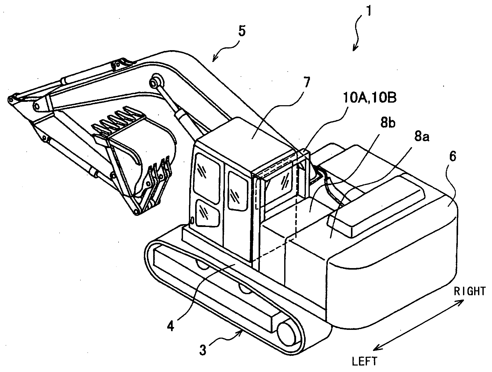
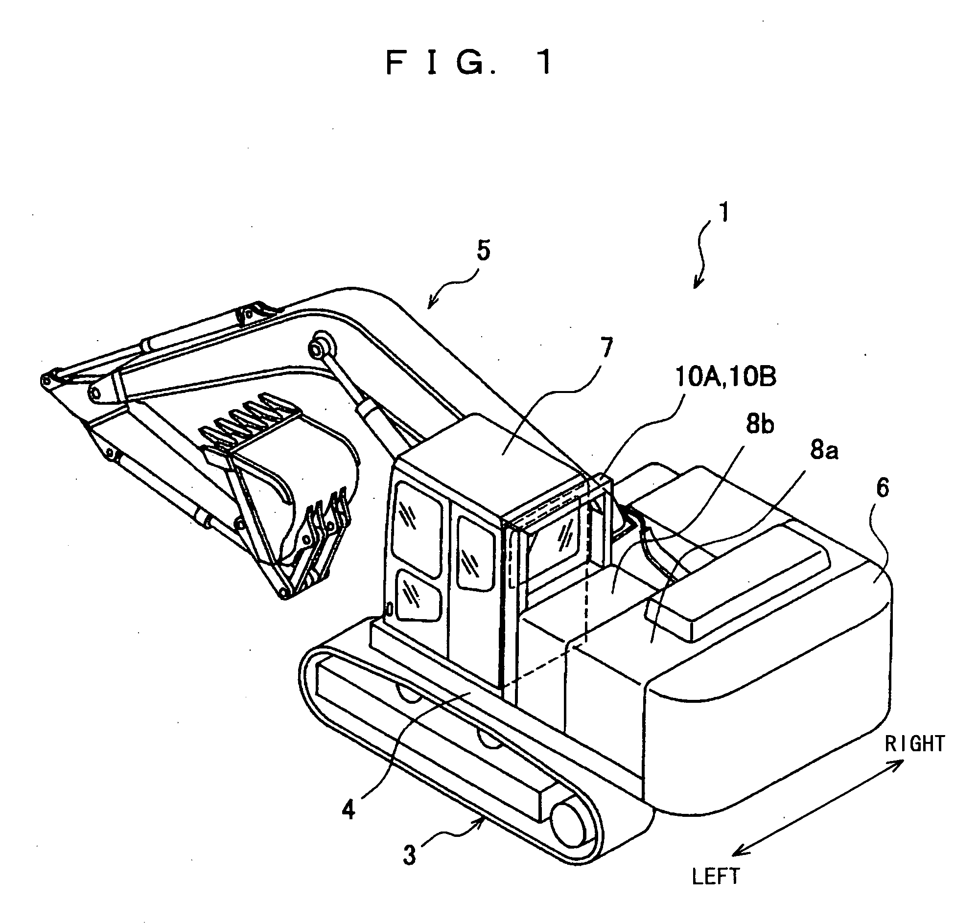
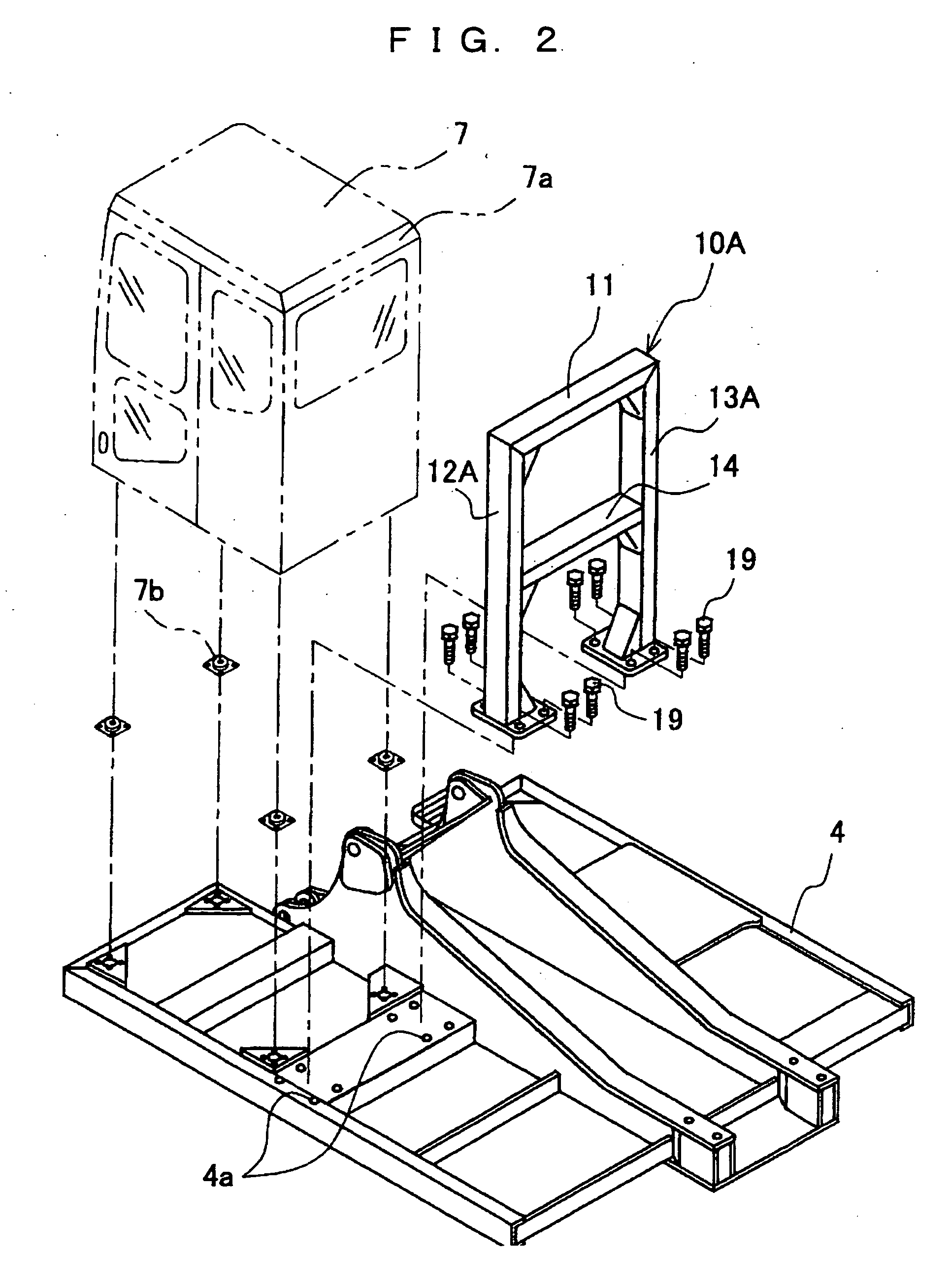
[0032] (1) When the hydraulic excavator 1 rolls over, the operator's cab protection member 11 of the portal frame 10A and the working machine 5 is in contact with the ground, whereby the hydraulic excavator 1 is supported by the portal frame 10A and the working machine 5, and therefore deformation of the operator's cab 7 which is located between the portal frame 10A and the working machine 5 is prevented or restrained. As a result, the operator space inside the operator's cab 7 is secured.

[0033] (2) At this time, the portal frame 10A is placed in close vicinity to the rear surface of the operator's cab 7 to place the operator's cab protection member 11. As a result, the strong operator's cab protection frame 10A can be placed easily in small to large construction equipment.

[0034] (3) The operator's cab protection frame 10A is placed in close vicinity to the rear surface of ...

second embodiment

[0036] Based on FIG. 3, a second embodiment will be explained. A portal frame 10B includes the operator's cab protection member 11 placed in close vicinity to the upper side 7a of the rear surface of the operator's cab 7, the left and the right supporting columns 12A and 13B (supporting members 12A and 13B) which are mounted to the left and the right of the operator's cab protection member 11 and are provided upright in the vertical direction, and a reinforcement member 14 mounted in between the intermediate portions in the vertical direction of the left and right supporting columns 12A and 13B. A mounting seat 4c is placed on an outside surface of the vertical plate member 4b at the side of the operator's cab 7 among a pair of left and right vertical plate members 4b and 4b which are provided at the upper revolving superstructure frame 4 and support a base end portion of the working machine 5 (see FIG. 1) to be swingable up and down. The supporting column 13B placed at an inner sid...

third embodiment

[0040] Based on FIG. 4, a third embodiment will be explained. A portal frame 10C (an operator's cab protection frame 10C) includes the operator's cab protection member 11 placed in close vicinity to the upper side 7a of the rear surface of the operator's cab 7, left and right supporting columns 12B and 13C (supporting members 12B and 13C) which are mounted to the left and the right of the operator's cab protection member 11 and are provided upright in the vertical direction, and the reinforcement member 14 mounted in between the intermediate portions in the vertical direction of the left and the right supporting columns 12B and 13C. The portal frame 10C is placed to straddle the machine room 8b adjacent to a rear side of the operator's cab 7. The left and the right supporting columns 12B and 13C of the portal frame 10C are respectively fastened to a predetermined numbers of threaded holes 4f of a mounting seat 4e which is placed at the outside surface of the upper revolving superstr...


PUM


Abstract

Construction equipment of which protection structure for an operator's cab when rolling over can be constituted to be favorable in visibility, transportability, and assembling and disassembling operability is provided. For this purpose, the construction equipment includes an upper revolving superstructure frame (4) rotatably loaded on a base carrier (3); and an operator's cab (7), a working machine (5) and a counterweight (6) which are provided on the upper revolving superstructure frame. Further, an operator's cab protection frame (10A), which includes an operator's cab protection member (11), supporting members (12A, 13A) for supporting the operator's cab protection member and mounting members (19, 19) with which base end portions of the supporting members are mounted to a vehicle body, is mounted to the upper revolving superstructure frame, and is provided upright behind the operator's cab.

Description

TECHNICAL FIELD [0001] The present invention relates to construction equipment, and particularly relates to construction equipment having a protection structure for an operator's cab at a time of rolling over. BACKGROUND ART [0002] Various kinds of means for preventing or restraining deformation of an operator's cab to protect the operator when construction equipment turns over (refers to the state in which the construction equipment turns about 90 degrees) or rolls over (refers to the state in which the construction equipment turns about 180 degrees or more) are conventionally proposed in the construction equipment. A structure in which a shock absorber is attached to a side surface portion of the operator's cab provided at an upper part of a vehicle body capable of being self-propelled to relieve an impact load which acts on the operator's cab by the shock absorber when the construction equipment turns over is described on pages 2 to 3 and in FIG. 4 of Japanese Patent Application ...

Claims


Application Information

Patent Timeline
Patent Type & Authority Applications(United States)
IPC IPC(8): E02F9/16E02F9/18E02F9/24
CPCE02F9/24E02F9/163E02F9/16
Inventor MORI, TADASHI
Owner KOMATSU LTD
Why Eureka
Try Eureka