Crankcase ventilation system

a ventilation system and crankcase technology, applied in the direction of combustion engines, charge feed systems, non-fuel substance addition to fuel, etc., can solve the problems of difficulty in ccv systems, unsatisfactory methods, internal crankcase pressure will inherently rise, etc., and achieve the effect of improving crankcase ventilation

Inactive Publication Date: 2005-01-06
CUMMINS INC
View PDF7 Cites 37 Cited by
  • Summary
  • Abstract
  • Description
  • Claims
  • Application Information

AI Technical Summary

Benefits of technology

[0007] Another object of the present invention is to provide an improved crankcase ventilation system for a turbocharged ...

Problems solved by technology

Because of these blow-by gases, the internal crankcase pressure will inherently rise promoting oil leakage from the crankcase to the surrounding environment.
This design creates difficulties for CCV systems as the lower pressure blow-by gases cannot be i...

Method used


Image

  • Crankcase ventilation system
  • Crankcase ventilation system
  • Crankcase ventilation system

Examples


Embodiment Construction

[0011] For the purposes of promoting understanding of the principles of the invention, reference will now be made to the embodiments illustrated in the drawings and specific language will be used to describe the same. It will nevertheless be understood that no limitation of the scope of the invention is hereby intended and alterations and modifications in the illustrated device, and further applications of the principles of the present invention as illustrated herein being contemplated as would normally occur to one skilled in the art to which the invention relates.

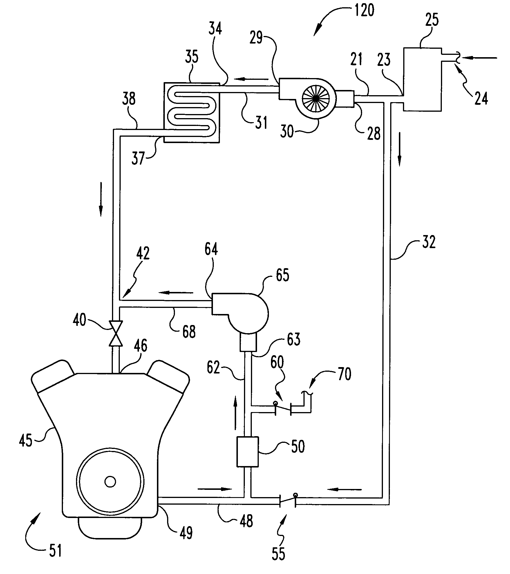
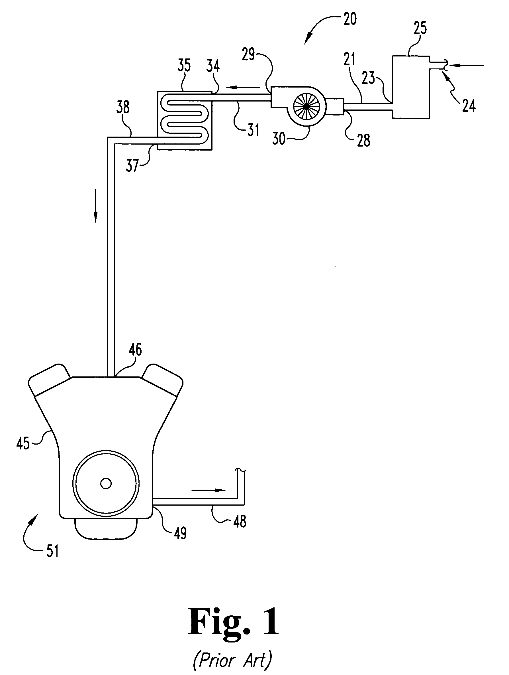
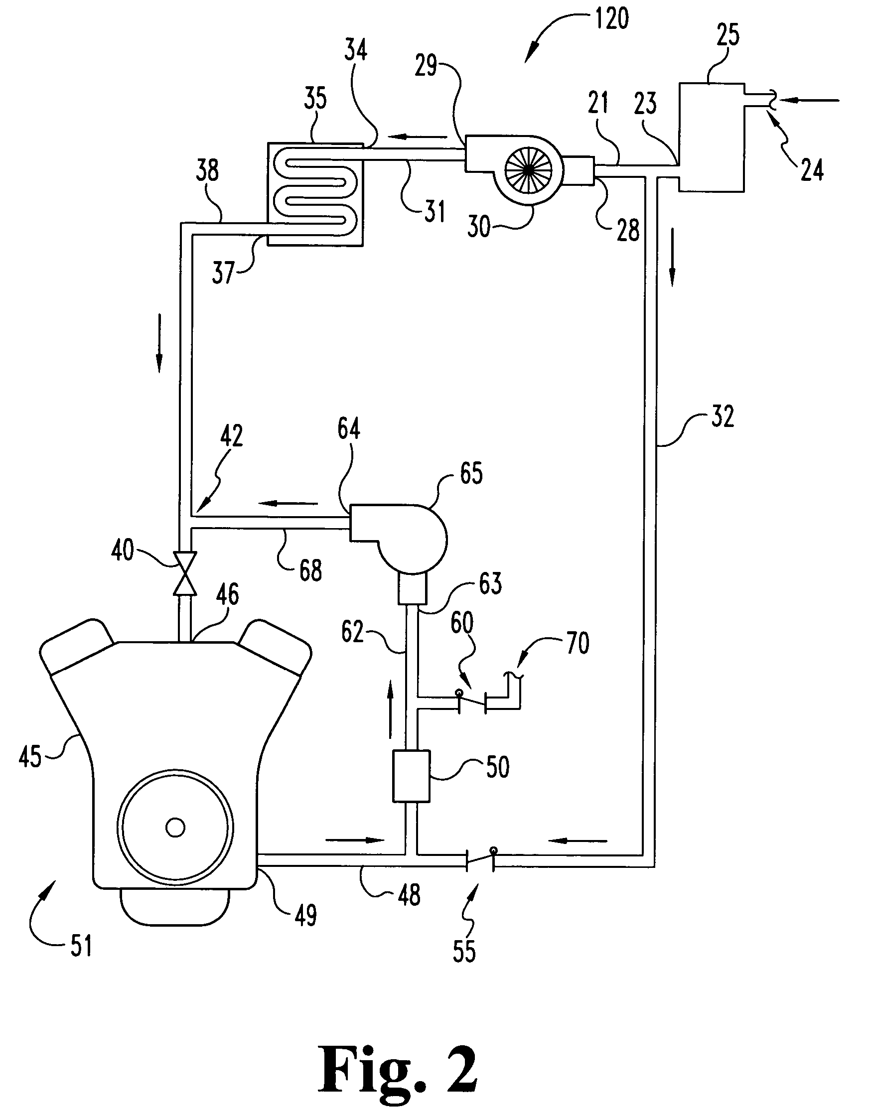
[0012]FIG. 1 is a diagrammatic representation of a turbocharged internal combustion engine ventilation system 20. System 20 includes an aircleaner 25, a turbocharger 30, an optional aftercooler 35 and a diesel engine 51. Aircleaner 25 includes an inlet 24 and an outlet 23. Turbocharger 30 includes an inlet 28 and an outlet 29. Aircleaner outlet 23 is connected to turbocharger inlet 28 by a conduit 21 and are effectively ...


PUM


Abstract

An improved crankcase ventilation system for a vehicle which includes an air compressor to route crankcase gases to the intake manifold for combustion. The primary vehicle components include and aircleaner, a turbocharger compressor positioned downstream from the aircleaner, an optional aftercooler positioned downstream from the turbocharger compressor, and an engine having an intake manifold and a crankcase equipped with a breather port for venting crankcase gases. Crankcase gases are vented through the breather port to the air compressor. Clean air from downstream of the aircleaner but upstream of the turbocharger compressor is drawn into the air compressor as needed to prevent the air compressor from drawing too much crankcase gas and reducing the internal pressure of the crankcase to undesirable levels. The pressurized crankcase gases are introduced into the intake air stream downstream of the aftercooler and upstream of the intake manifold so as to prevent fouling of the turbocharger compressor and aftercooler by contaminants in the crankcase gases. The crankcase gases are then combusted in the engine and not vented directly to the environment.

Description

FIELD OF THE INVENTION [0001] The present invention relates generally to the regulation of crankcase pressures in internal combustion engines and, in particular, to a crankcase ventilation system which returns crankcase gasses to the engine for combustion. BACKGROUND OF THE INVENTION [0002] In most internal combustion engines, it is desirable to maintain the pressure within the crankcase at a level equal to or slightly less than atmospheric pressure to reduce leaks through gaskets and seals from the crankcase to the atmosphere. As is well known, in an internal combustion engine, so-called blow-by gases are emitted in the crankcase as a result of leaks of the air-fuel intake mixture and combustion gases through the clearances around piston rings during the compression, combustion and / or exhaust cycles. Because of these blow-by gases, the internal crankcase pressure will inherently rise promoting oil leakage from the crankcase to the surrounding environment. [0003] Traditionally, exce...

Claims


Application Information

Patent Timeline
IPC IPC(8): F02M25/06
CPCF01M2013/027Y02T10/121F02M25/06Y02T10/12
Inventor NORRICK, DANIEL A.
Owner CUMMINS INC
Why Eureka
Try Eureka