Counting system and counting method

a technology applied in the field of counting system and counting method, can solve the problems of inability to detect the passage of each of the plurality of objects to be counted, inability to perform high-speed counting process, and relatively heavy computation load, and achieve the effect of light computation load

Inactive Publication Date: 2005-01-06
KONICA MINOLTA INC
View PDF4 Cites 20 Cited by
  • Summary
  • Abstract
  • Description
  • Claims
  • Application Information

AI Technical Summary

Benefits of technology

Therefore, an object of the present invention is to provide a technique capable of achieving a very light computation load and counting the num

Problems solved by technology

In this method, however, in the case where a plurality of objects to be counted are lined in the width direction of the path and pass between the units simultaneously, passage of each of the plurality of objects to be counted cannot be detected.
However, the w

Method used


Image

  • Counting system and counting method
  • Counting system and counting method
  • Counting system and counting method

Examples


Embodiment Construction

Hereinafter, preferred embodiments of the invention will be described with reference to the drawings.

1. First Preferred Embodiment

1-1. System Configuration

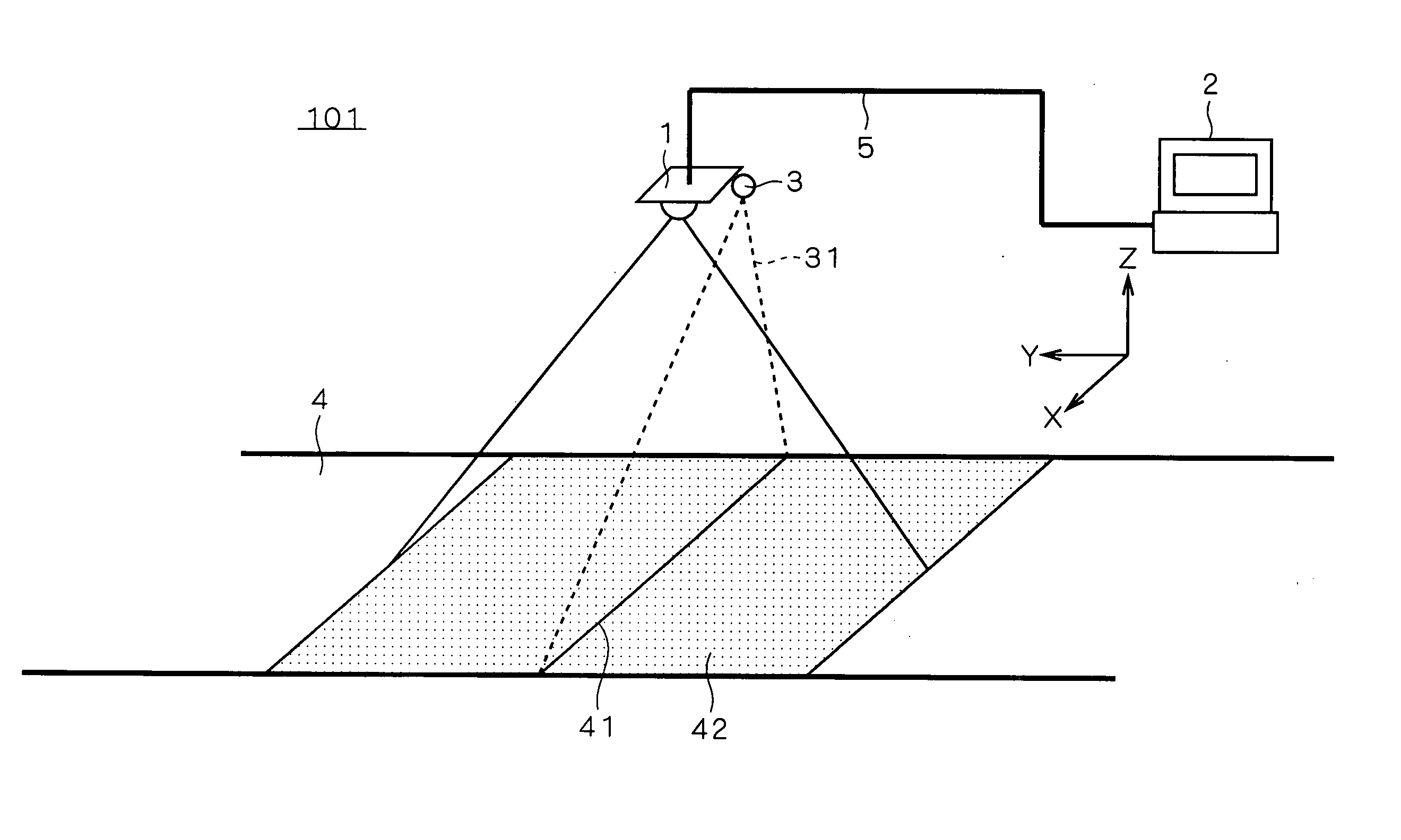
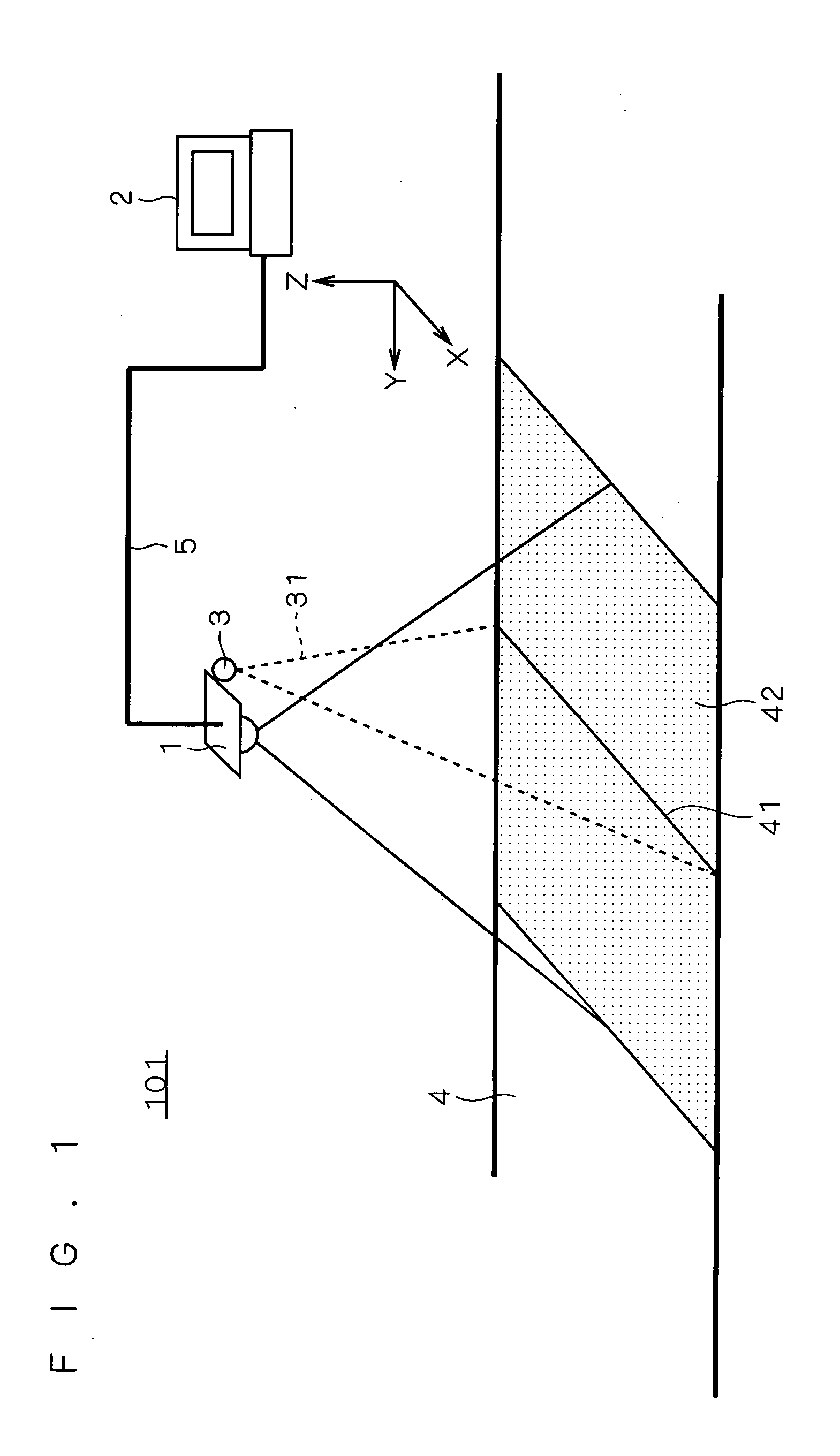
FIG. 1 is a schematic configuration diagram of a counting system of a first preferred embodiment of the present invention. This counting system 101 is for counting the number of passing persons as objects to be counted in a path 4. As shown in the diagram, the counting system 101 has a laser 3 as a light source for emitting a slit ray 31, an image capturing apparatus 1 for capturing an area irradiated with the slit ray 31, and a monitoring apparatus 2 for displaying the number of passing persons counted on the basis of a captured image. In the following description, at the time of showing directions and orientations, an XYZ three-dimensional rectangular coordinate system shown in the diagram is properly used. The XYZ axes are fixed relative to the path 4. The X-axis direction is the width direction of the path 4 (direction or...


PUM


Abstract

A counting system is for counting the number of persons passing a monitor line set in the width direction of a path, and has a laser for irradiating the monitor line with a slit ray, and an image capturing apparatus for photographing an area including the monitor line. In the image capturing apparatus, one-dimensional data indicative of a position in which the slit ray is interrupted on the monitor line is generated from an image obtained by the photographing. On the basis of the one-dimensional data, the number of passing persons is counted. By counting the number of passing persons with the one-dimensional data, a very light computation load for the counting can be achieved.

Description

This application is based on application No. 2003-191809 filed in Japan, the contents of which are hereby incorporated by reference. BACKGROUND OF THE INVENTION 1. Field of the Invention The present invention relates to a technique of counting the number of passing objects to be counted in a path. 2. Description of the Background Art Conventionally, various methods of detecting passing of an object to be counted such as a person in a path and counting the number of passing times have been proposed. As an example, there is a known method of disposing a projecting unit for projecting a light beam and a light receiving unit for receiving the light beam while sandwiching a path and detecting passing of a person by using property that a person interrupts a light beam when the person passes the path. Another known method is a method of emitting a slit ray in the width direction of a path, photographing an area of the position to be irradiated with the slit ray to obtain a two-dimen...

Claims


Application Information

Patent Timeline
IPC IPC(8): G01V8/10G06M1/10G06M7/00G06T1/00G07C9/00
CPCG06M1/101G07C9/00G06M7/00
Inventor SUMITOMO, HIRONORIFUJIWARA, KOJI
Owner KONICA MINOLTA INC
Why Eureka
Try Eureka