Vehicle slip state determination system and traveling state control system

a technology of vehicle slip state and determination system, which is applied in the direction of process and machine control, instruments, etc., can solve the problems of inability to estimate the speed of the vehicle, inability to execute abs control, and inability to accurately determine the slip state of the vehicle. , to achieve the effect of accurately determining the slip state of the vehicl

Inactive Publication Date: 2006-03-09
ADVICS CO LTD
View PDF15 Cites 20 Cited by
  • Summary
  • Abstract
  • Description
  • Claims
  • Application Information

AI Technical Summary

Benefits of technology

[0012] According to a second aspect of the present invention, the determination range defined by the lower limit value and the upper limit value larger than the lower limit value each as the predetermined value in accordance with the braking state is set. If the deceleration deviates from the determination r

Problems solved by technology

In the case where the wheel is brought into the slip state without generating the wheel speed difference between the front and rear wheels as described above, the vehicle speed cannot be estimated, thus failing to determine the slip state of the vehicle.
It is not practical to execute the ABS control using the slip ratio derived from the estimated vehicle speed far deviat

Method used


Image

  • Vehicle slip state determination system and traveling state control system
  • Vehicle slip state determination system and traveling state control system
  • Vehicle slip state determination system and traveling state control system

Examples


Embodiment Construction

[0026] The present invention will be described further with reference to various embodiments in the drawings.

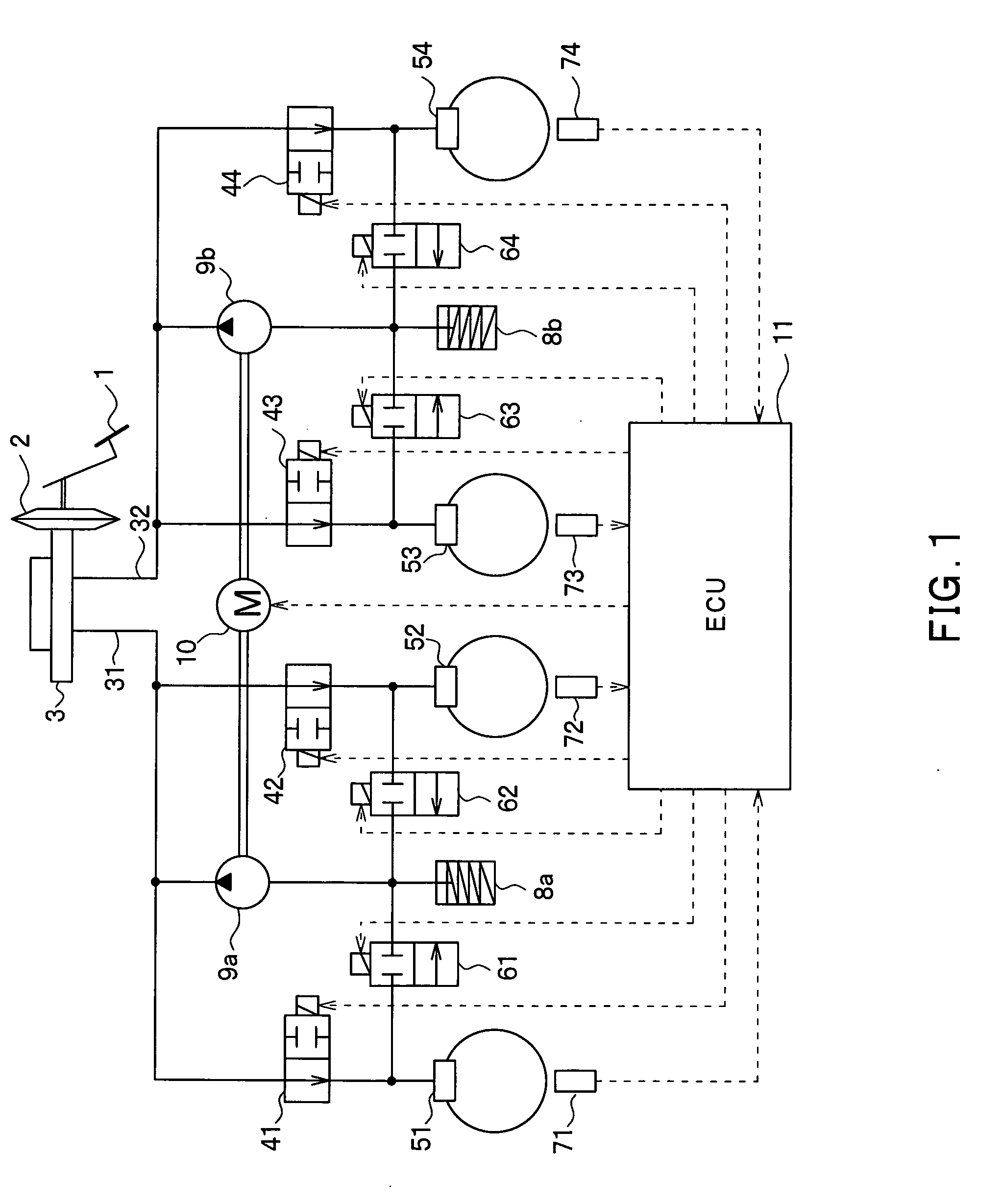
[0027] An embodiment structured by applying a vehicle slip determination system of the present invention will be described referring to the drawings. FIG. 1 is a schematic view that shows a structure of a brake unit of the embodiment.

[0028] Referring to FIG. 1, a brake pedal 1 is connected to a master cylinder (hereinafter referred to as M / C) 3 via a servo unit 2 such that hydraulic pressure is generated upon depression of the brake pedal 1. The generated hydraulic pressure is supplied to each of wheel cylinders (hereinafter W / C) 51, 52, 53 and 54 respectively provided on the wheels (left front wheel FL, right front wheel FR, left rear wheel RL, and right rear wheel RR) via a first brake system 31 and a second brake system 32 each connected to the M / C 3 as an X piping. The structure of the first brake system is the same as that of the second brake system 32. Accordingly the...


PUM


Abstract

A vehicle slip state determination system serves to calculate an estimated vehicle speed VB, an estimated vehicle deceleration in the vehicle speed DVB, and each of wheel speed differences between right front and rear wheels and between left front and rear wheels ΔVR, ΔVL, respectively. The wheel speed difference ΔVR, ΔVL are divided into three ranges, that is, range 1, range 2, and range 3 by the speed difference upper and lower limit values JVUP and JVLO, each of which is a linear function value with respect to the estimated vehicle deceleration DVB. In the ranges 1 and 3, the vehicle traveling on the road with the low friction coefficient μ is brought into the slip state where four wheels are slipped. If the wheel speed difference at a predetermined estimated vehicle deceleration deviates from a determination range defined by the upper and lower limit values, the slip state of the vehicle, that is, the condition where the vehicle is traveling on the road with the low friction coefficient μ is determined.

Description

FIELD OF THE INVENTION [0001] The present invention relates to a vehicle slip state determination system that determines a slip state of a vehicle, and is preferably applicable to a four-wheel-drive vehicle, an anti-lock brake control system (hereinafter referred to as ABS control system), a traction control system and the like. BACKGROUND OF THE INVENTION [0002] A vehicle equipped with an ABS control system has been generally designed to be controlled on the assumption that the front wheel is locked prior to the rear wheel. Japanese Patent Application Laid-Open Hei 7-159308 discloses that the wheel speed difference between the front and rear wheels is calculated, and a friction coefficient μ on the road surface is estimated based on a time gradient obtained when the change ratio of the wheel speed difference becomes equal to or larger than a predetermined value. The ABS control operation is executed based on the resultant friction coefficient μ. [0003] In the case where the frictio...

Claims


Application Information

Patent Timeline
IPC IPC(8): G05D1/06
CPCB60T8/17616B60W40/103B60W10/18B60W10/06
Inventor WATANABE, TAKASHIABE, YASUHIROKUDO, KEN
Owner ADVICS CO LTD
Why Eureka
Try Eureka