

System bridge and timeclock for RF controlled lighting systems
a technology of lighting control system and time clock, which is applied in the direction of electric controllers, ignition automatic control, instruments, etc., can solve the problems of increasing costs, requiring complicated and/or cumbersome retrofitting, and reducing so as to minimize message collisions and avoid data collisions. , the effect of minimizing the possibility of subnet communication
- Summary
- Abstract
- Description
- Claims
- Application Information
AI Technical Summary
Benefits of technology
Problems solved by technology
Method used
Image

Examples
Embodiment Construction
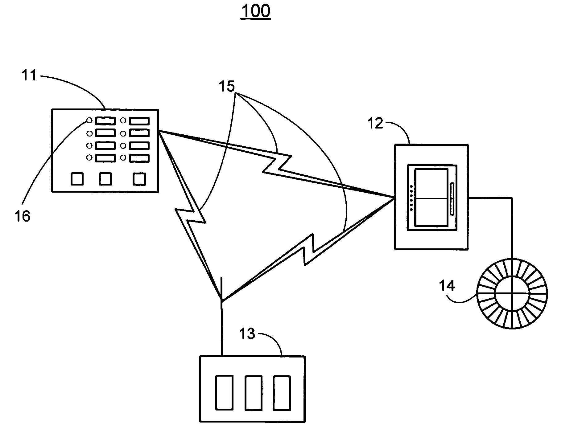
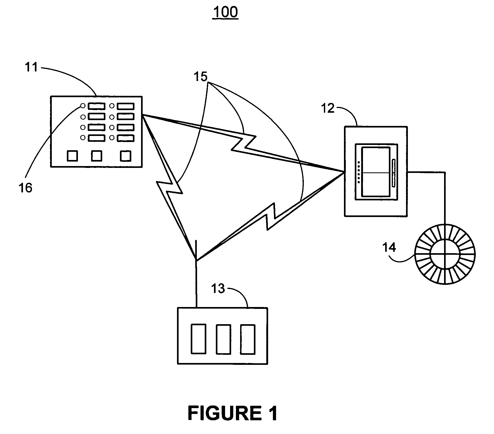
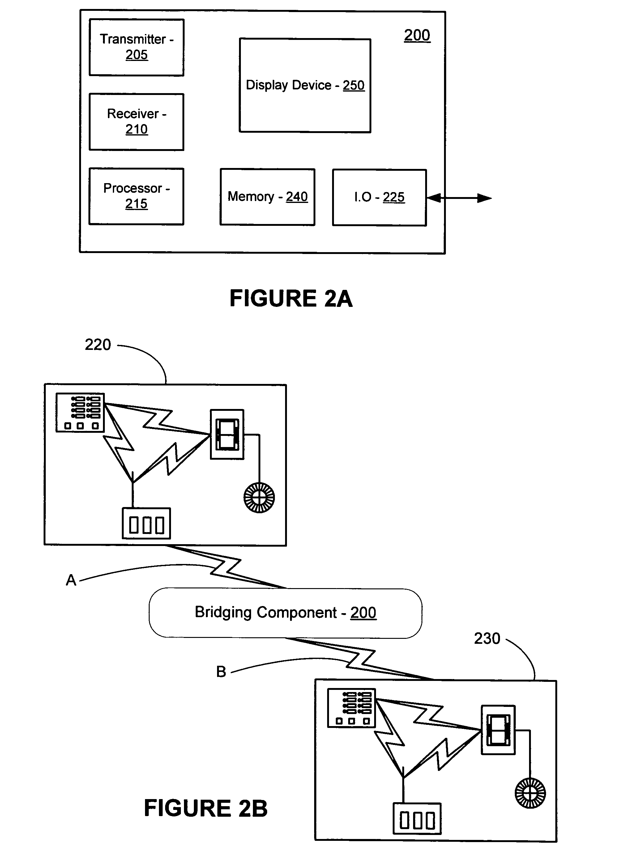
[0022] An embodiment of the present invention relates to operatively interconnecting two or more RF lighting control systems that are operating in close proximity to each other on the same RF. Close proximity in such an embodiment refers to the ability of at least one device of one RF lighting control system to transmit a RF signal that may be received by at least one device of a second RF lighting control system. As may be appreciated, the RF signals used by such lighting control systems may be of any frequency that is suitable for the intended location and use of the lighting control system. For example, the frequency may be chosen to comply with FCC regulations, to avoid interference with other devices located in the area in which the lighting control system is operating, or in accordance with other considerations.
[0023] As noted above, an embodiment of the present invention relates to lighting control systems that may be employed in buildings or the like. Examples of such light...
PUM
 Abstract
Description
Claims
Application Information