Data transferring apparatus for transferring liquid ejection data and a liquid ejecting apparatus

a data transfer and liquid ejection technology, applied in the field of data transferring apparatus for transferring liquid ejection data and liquid ejection apparatus, can solve the problems of increasing the cost of the data transferring apparatus. , the effect of increasing the cos

Inactive Publication Date: 2005-01-06
SEIKO EPSON CORP
View PDF8 Cites 13 Cited by
  • Summary
  • Abstract
  • Description
  • Claims
  • Application Information

AI Technical Summary

Benefits of technology

[0015] It is an object of the present invention to realize the development process of compressed data at high speed and the data transfer to the liquid ejecting head at high speed at low cost, so that it is possible to considerably increase the liquid ejection speed of the liquid ejecting apparatus at low cost compared with that of the prior art.

Problems solved by technology

First, since the compressed recording data is developed (extracted) by a program one byte each, it is impossible to process a great quantity of compressed data at high speed.
If the microprocessor 11, which operates at high speed clock and has a high process capacity, is used, speeding up can be achieved, however, that causes such problem as the cost of the data transferring apparatus 10 gets extremely high if this expensive microprocessor 11 is mounted.
In addition, since both the data transfer to the RAM 12 and the data transfer from the RAM 12 are performed through the microprocessor 11, while the microprocessor 11 executes other data processes or calculations such as the microprocessor 11 fetches programs from the RAM 12, the data transfer might get into a waiting state, and thus the data transfer delay occurs, so that the data transfer at high speed can not be achieved.
Further, in regard to the prior art disclosed in the Japanese Patent Application Publication No. 3251053 described above, the compressed recording data is also developed (extracted) by a program one byte each, so that a great amount of compressed data cannot be developed at high speed.
Therefore, in regard to the liquid ejecting apparatus such as the recording apparatus, which executes recording by developing the compressed recording data transferred from an information processing apparatus and then transferring it to the recording head, the speed of ejecting liquid cannot be enhanced because the process to develop the compressed data is still slow though the data transfer process can be performed at high speed.

Method used


Image

  • Data transferring apparatus for transferring liquid ejection data and a liquid ejecting apparatus
  • Data transferring apparatus for transferring liquid ejection data and a liquid ejecting apparatus
  • Data transferring apparatus for transferring liquid ejection data and a liquid ejecting apparatus

Examples


first embodiment

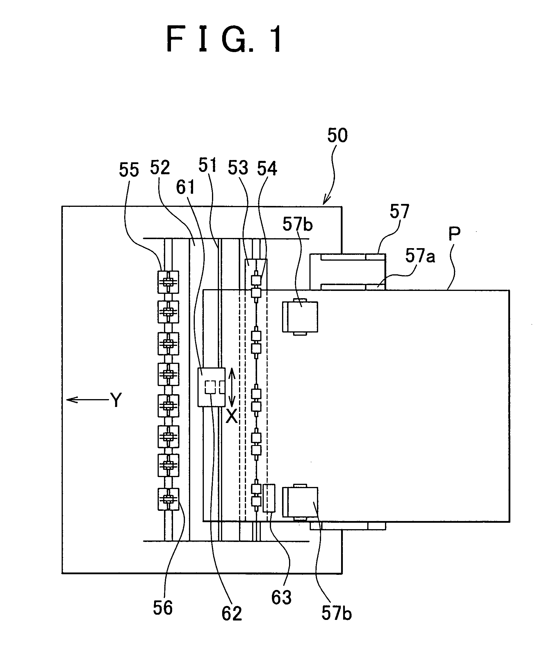
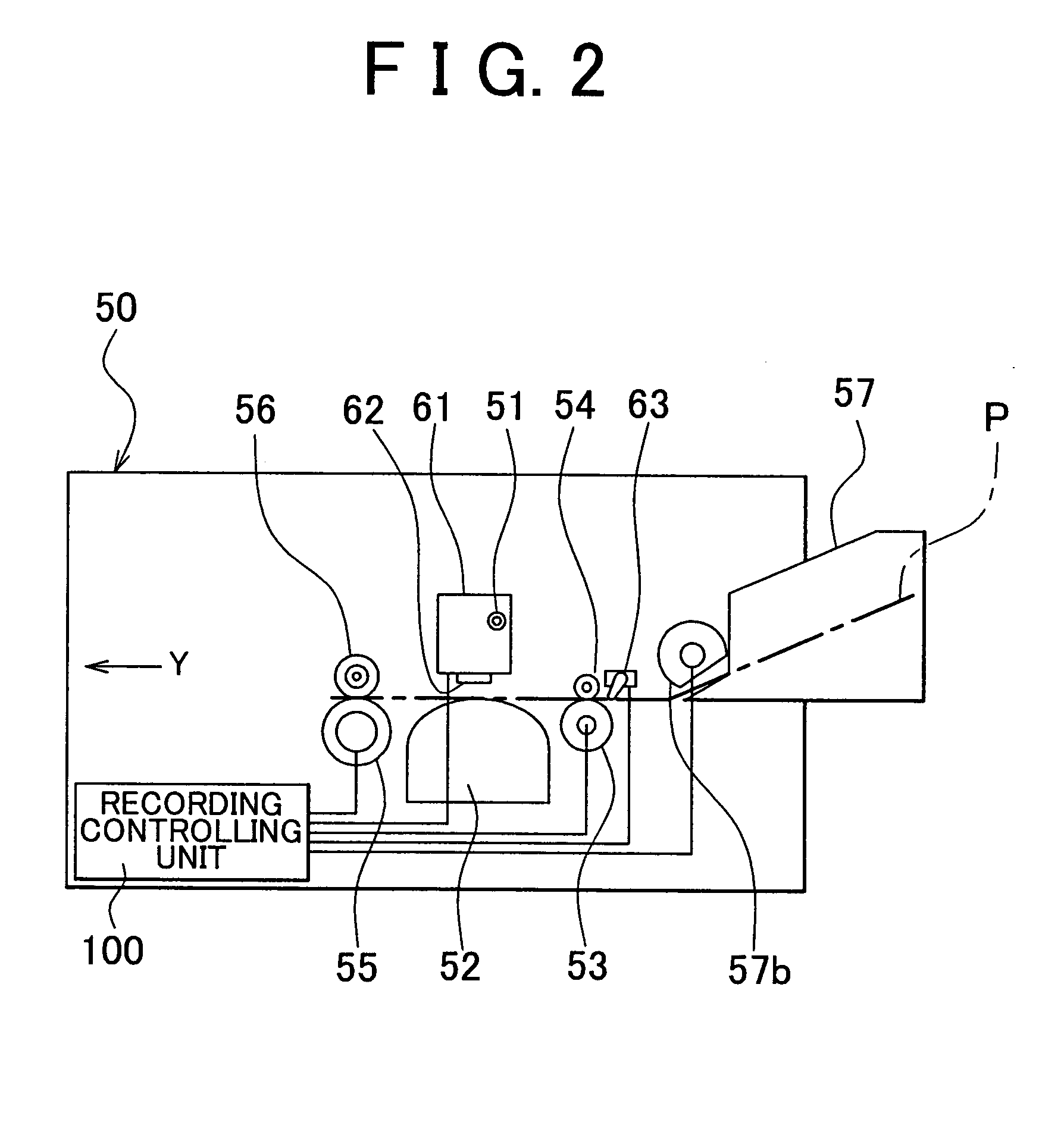
[0069] To begin with, the inkjet type recording apparatus will be described as a “liquid ejecting apparatus” relating to the present invention. FIG. 1 is a schematic plan view of an inkjet type recording apparatus relating to the present invention, and FIG. 2 is a side view of it.

[0070] In the inkjet type recording apparatus 50, a carriage 61 is provided to move along a main scanning direction X as a recording means, which performs recording on recording papers P, rotatably supported by carriage guide shaft 51. On the carriage 61, a recording head 62 is mounted as a “liquid ejecting head”, which performs recording by ejecting ink onto the recording papers P. Opposite to the recording head 62, a platen 52 is provided to control a gap between the head surface of the recording head 62 and the recording papers P. And, recording on the recording papers P is performed by repeating an operation of transferring the recording papers P between the carriage 61 and the platen 52 in a sub scanni...

second embodiment

[0106]FIG. 10 is a block diagram showing the data transferring apparatus 10. FIG. 11 is a timing chart schematically showing the flow of data in regard to the data transferring apparatus 10.

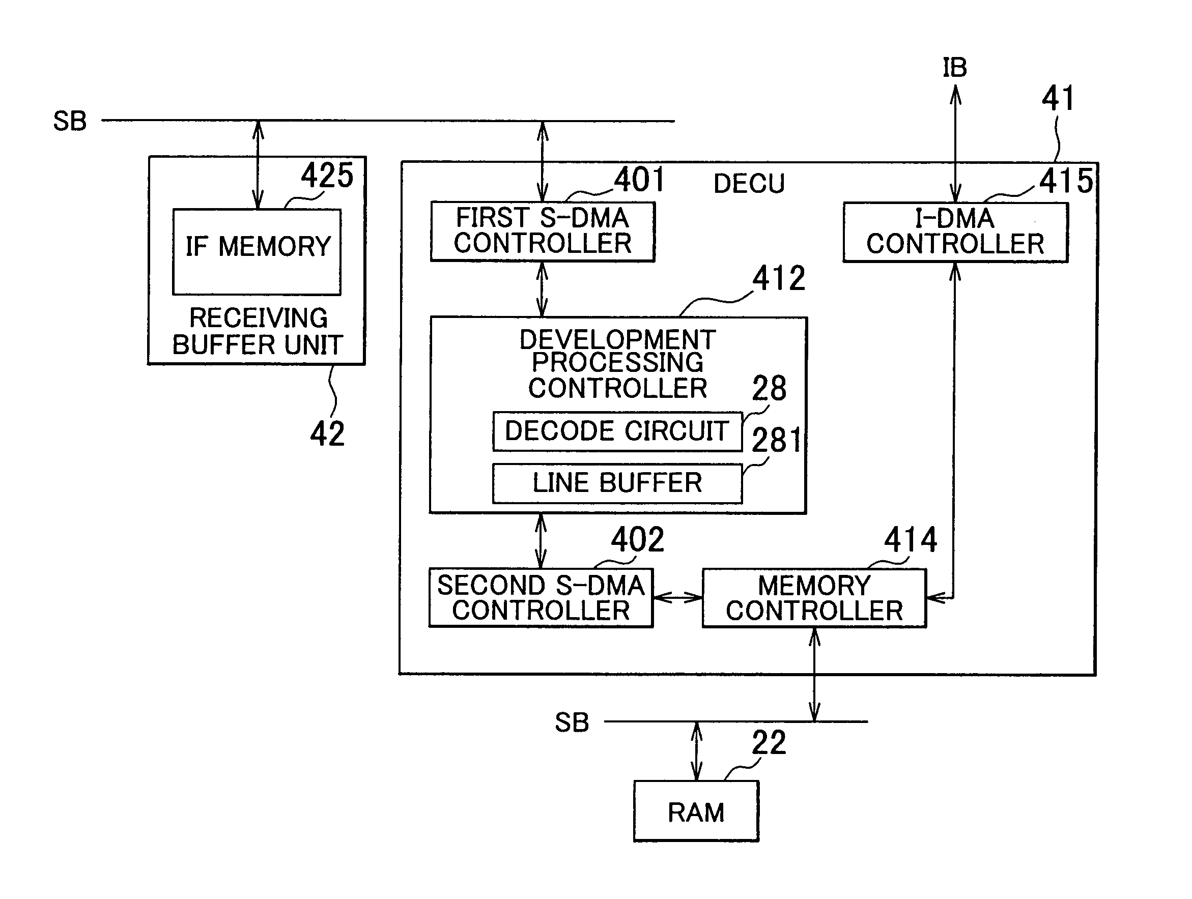
[0107] The interface unit 27 has a means for sending and receiving data to and from the information processing apparatus 200 taking the information processing apparatus 200 as a host apparatus in a predetermined data transfer sequence, and receives the record controlling data from the information processing apparatus 200 to allow the recording controlling unit 100 to control recording. The record controlling data includes a command and a remote command on which the MPU 24 performs command analysis and the compressed recording data on which the DECU 41 performs hardware development, and it is sent by the information processing apparatus 200 as a header of 6 bytes is added to it for each data block. The interface unit 27 DMA-transfers the received record controlling data to the receiving buffer uni...

third embodiment

[0120]FIG. 14 is a block diagram showing the data transferring apparatus 10.

[0121] The interface unit 27 has an I / F block 271 as a means for sending and receiving data to and from the information processing apparatus 200 taking the information processing apparatus 200 as a host apparatus in a predetermined data transfer sequence, a command storing register 426 in which the command is stored, a header analyzing block 423 as a “header analyzing means” for analyzing the header of the record controlling data, a change controlling block 422 as a “command separating means” for separating the command from the record controlling data based on the analysis result of the header analyzing block 423, storing the command in the command storing register 426, transferring the record controlling data after command separation to the data transfer controlling block 424 and storing it in the IF memory 425 and a data transfer controlling block 424 as a “data transfer controlling means” for storing the ...


PUM


Abstract

A data transferring apparatus has an ASIC (Application Specific Integrated Circuit), and the ASIC incorporates an interface unit, a head controlling unit, a receiving buffer unit and a DECU, which are coupled to be capable of transferring data. The DECU incorporates a development processing controller having a decode circuit for performing hardware development on compressed recording data, and a line buffer storing developed recording data. The DECU and the head controlling unit are coupled by an internal bus IB in order to perform data transfer.

Description

BACKGROUND OF THE INVENTION [0001] This application claims priority from a Japanese Patent Application No. 2003-190388 filed on Jul. 2, 2003, the content of which is incorporated herein by reference. [0002] 1. Field of the Invention [0003] The present invention relates to a data transferring apparatus for transferring liquid ejection data and a liquid ejecting apparatus of liquid ejection data for transferring the liquid ejection data to a liquid ejecting head, wherein the liquid ejection data is inputted into the liquid ejecting apparatus which ejects a liquid such as ink from the liquid ejecting head onto a medium to be ejected. [0004] 2. Description of the Related Art [0005] A liquid ejecting apparatus called an inkjet type recording apparatus records image data by ejecting ink from a recording head onto recording papers. The inkjet type recording apparatus ejects ink droplets of plural colors from plural nozzle arrays, which are provided at the head face of the recording head, d...

Claims


Application Information

Patent Timeline
Patent Type & Authority Applications(United States)
IPC IPC(8): B41J29/38G06F13/00G06F13/28G06F13/36G06K15/10H04L12/00H04L12/40
CPCG06F13/28
Inventor KIMURA, MASAHIROFUKUMITSU, YASUNORI
Owner SEIKO EPSON CORP
Why Eureka
Try Eureka